Charging control device for charging electric vehicle

a charging control and electric vehicle technology, applied in the direction of charging stations, battery/cell propulsion, transportation and packaging, etc., can solve the problem of unnecessari waste of current, and achieve the effect of reducing manufacturing costs, simplifying the structure of charging control devices, and simplifying the structure of electric vehicles

Active Publication Date: 2021-12-07
LG INNOTEK CO LTD
View PDF20 Cites 2 Cited by
  • Summary
  • Abstract
  • Description
  • Claims
  • Application Information

AI Technical Summary

Benefits of technology

[0029]According to an embodiment, since a control signal for instructing to start charging and a control signal for instructing to finish charging can be monitored through one line, a structure of a charging control device can be simplified, a structure of an electric vehicle can also be simplified, and thus manufacturing costs can be reduced.
[0030]The charging control device does not unnecessarily consume a current while the electric vehicle is charged or is not charged. In particular, even in a case in which a control signal for instructing to finish charging cannot be transmitted normally to the charging control device because a user is not present at a time point at which charging should be finished, unnecessary consumption of current due to operation of a microcontroller unit (MCU) of the charging control device can be inhibited.

Problems solved by technology

Accordingly, in a case in which a user is not present at a time point at which the slow charging or fast charging is finished, since a process for finishing the charging cannot proceed normally, a state in which the EV is connected to a charging control device is maintained, and thus there is a problem in that a current is unnecessarily wasted.

Method used


Image

  • Charging control device for charging electric vehicle
  • Charging control device for charging electric vehicle
  • Charging control device for charging electric vehicle

Examples


Embodiment Construction

[0037]As the present invention allows for various changes and numerous embodiments, specific embodiments will be illustrated in the drawings and described in detail in the written description. However, this is not intended to limit the present invention to specific embodiments, and it is to be appreciated that all changes, equivalents, and substitutes that do not depart from the spirit and technical scope of the present invention are encompassed in the present invention.

[0038]It will be understood that, although the terms “first,”“second,” etc. may be used herein to describe various elements, these elements should not be limited by these terms. These terms are only used to distinguish one element from another. For example, a first element could be termed a second element, and a second element could similarly be termed a first element without departing from the scope of the present invention. As used herein, the term “and / or” includes combinations or any one of a plurality of associa...


PUM


Abstract

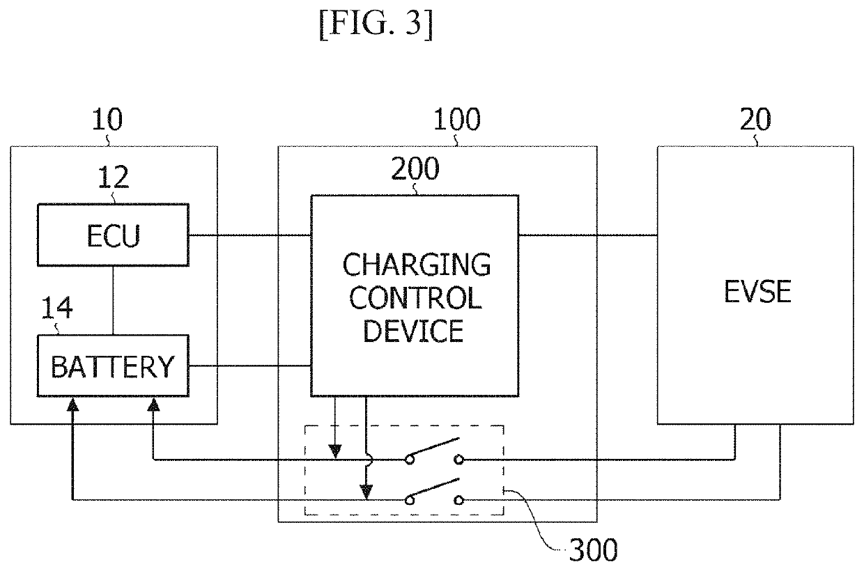
A charging control device for charging an electric vehicle according to one embodiment of the present invention comprises: a first switch unit for receiving a first control signal from the outside; a first control unit for receiving the first control signal through the first switch unit; a second switch unit for receiving a second control signal from the outside; a second control unit which is woken up by the first control unit and receives the second control signal through the second switch unit; and a motor control unit which is controlled by the second control unit and controls driving of a motor for a charging flap, wherein the second control unit disables the first switch and enables the second switch when the second control unit is woken up by the first control unit.

Description

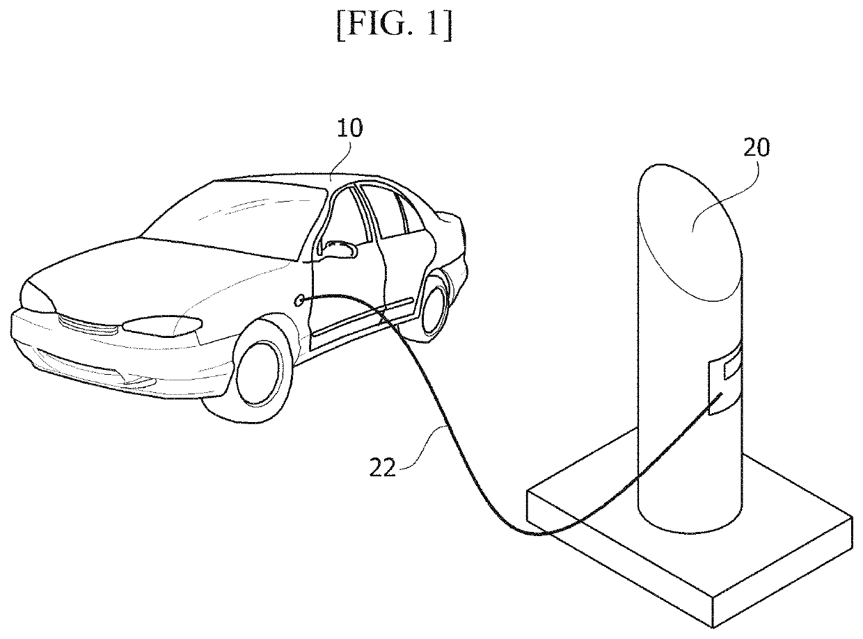
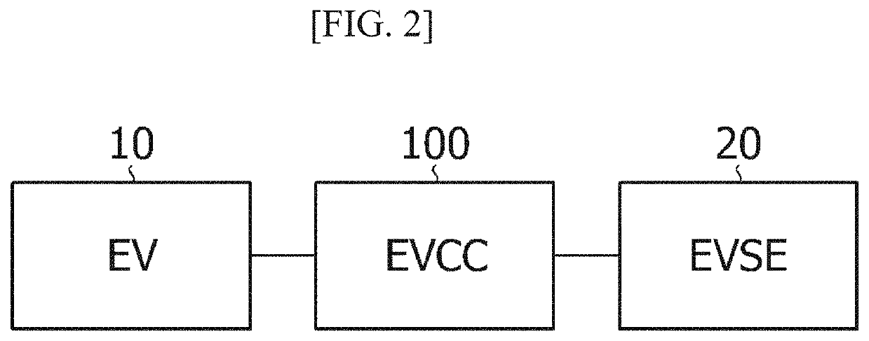
CROSS-REFERENCE TO RELATED APPLICATIONS[0001]This application is the U.S. national stage application of International Patent Application No. PCT / KR2018 / 001650, filed Feb. 7, 2018, which claims the benefit under 35 U.S.C. § 119 of Korean Patent Application No. 10-2017-0017434, filed Feb. 8, 2017, which are hereby incorporated by reference in their entirety.TECHNICAL FIELD[0002]The present invention relates to an electric vehicle, and more specifically, to charging of an electric vehicle.BACKGROUND ART[0003]Eco-friendly vehicles, such as electric vehicles (EVs) or plug-in hybrid electric vehicles (PHEVs), use electric vehicle supply equipment (EVSE) installed at supplies to charge batteries.[0004]To this end, an electric vehicle charging controller (EVCC) is installed in the EV and communicates with the EV and the EVSE to control charging of the EV.[0005]For example, when the EVCC receives a signal for instructing to start charging from the EV, the EVCC may control so as to start char...

Claims


Application Information

Patent Timeline
Patent Type & Authority Patents(United States)
IPC IPC(8): B60L50/60B60L53/66
CPCB60L50/60B60L53/66Y02T10/70Y02T90/16Y02T10/7072Y02T90/14Y02T90/12B60L53/16B60L53/18B60L53/305B60L53/00B60L53/14B60L53/30B60Y2200/91
Inventor KIM, HYOUNG DONG
Owner LG INNOTEK CO LTD
Why Eureka
Try Eureka