Computer to plate curing system

Inactive Publication Date: 2006-08-10
PRINTING RES
View PDF31 Cites 13 Cited by
  • Summary
  • Abstract
  • Description
  • Claims
  • Application Information

AI Technical Summary

Benefits of technology

[0013] A color densitometer may be used to measure curing based on color of a plate and a pow

Problems solved by technology

Imaging or exposing the printing plates causes the chemicals to react, leaving some regions exposed and other regions unexposed.
Some printing runs, however, produce so many copies that several sets of printing plates wear out and need replacing through the course of the printing run.
Ho

Method used


Image

  • Computer to plate curing system
  • Computer to plate curing system
  • Computer to plate curing system

Examples


Embodiment Construction

[0029] It should be understood at the outset that although an exemplary implementation of one embodiment of the present disclosure is illustrated below, the present system may be implemented using any number of techniques, whether currently known or in existence. The present disclosure should in no way be limited to the exemplary implementations, drawings, and techniques illustrated below, including the exemplary design and implementation illustrated and described herein.

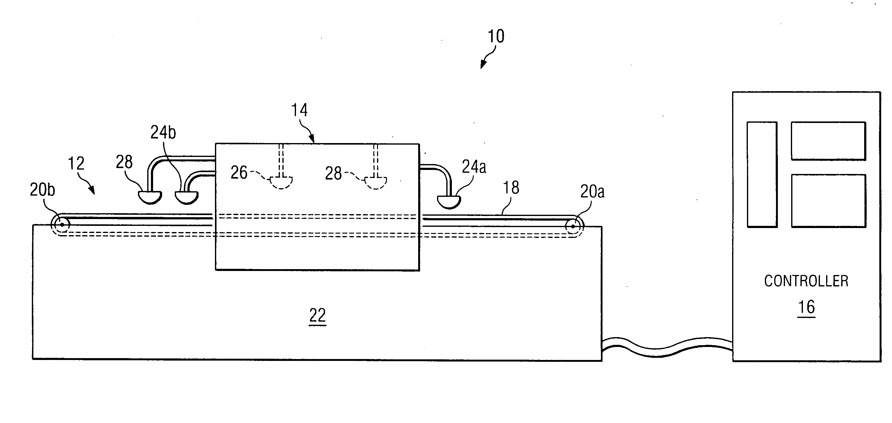
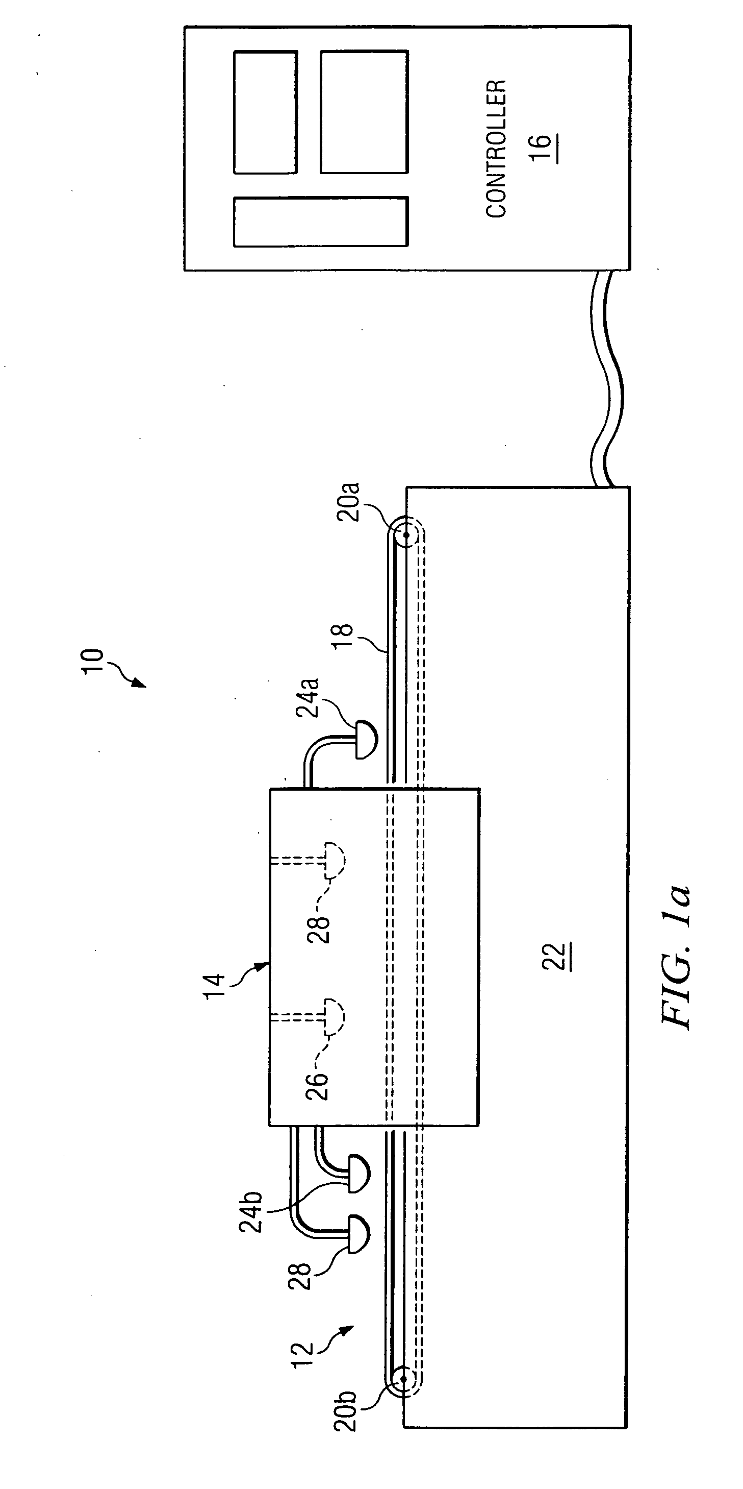
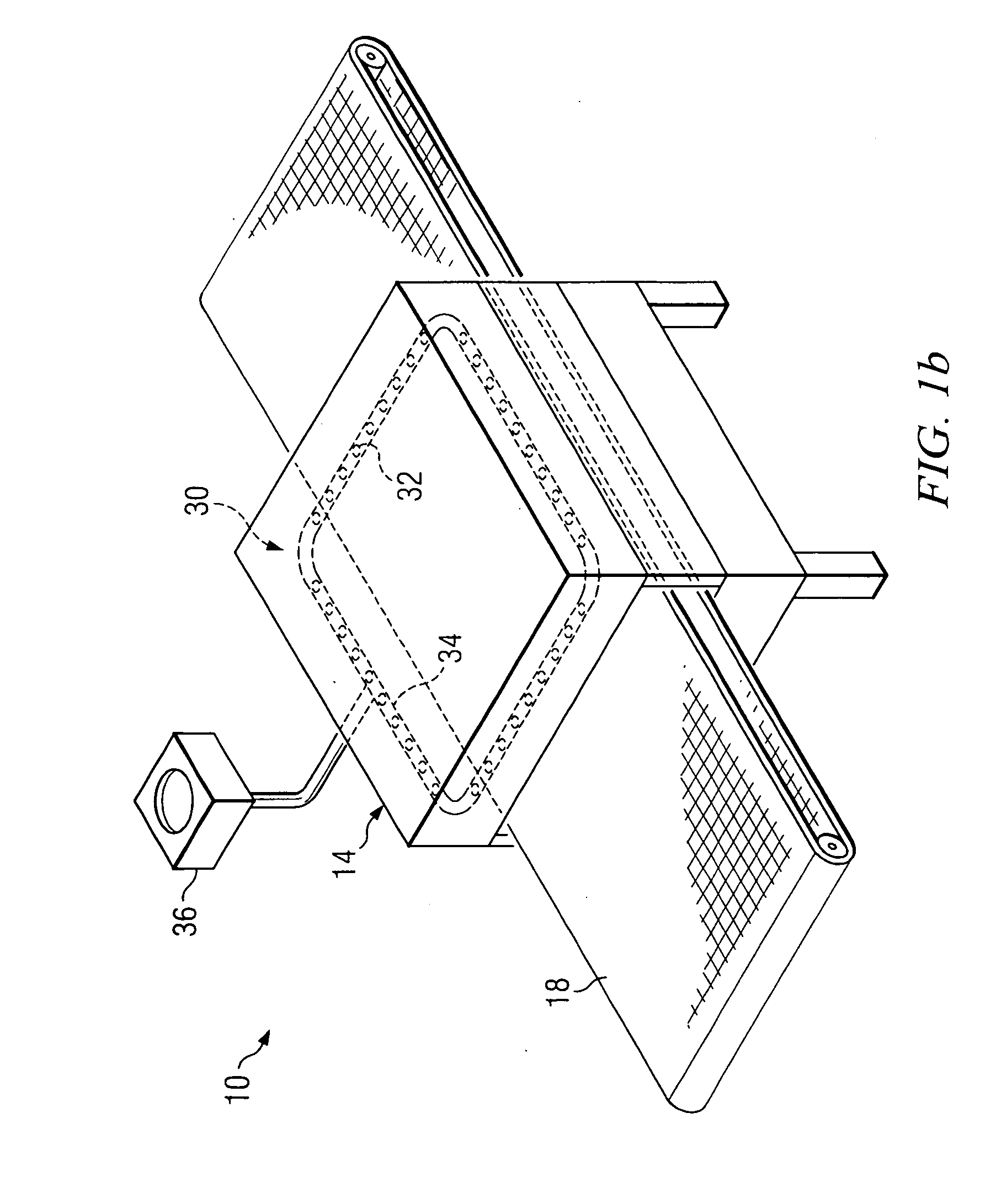
[0030] Some imaged and developed printing plates may experience longer run lives if they are first cured before use, for example by irradiating with heat or with ultraviolet light in accordance with the present invention. It is desirable to control the radiation applied to the printing plates carefully to properly cure the printing plates. Excessive radiation levels and / or irradiating too long may degrade the printing plate image and / or the metallurgical properties of the aluminum backing of the printing plate. For...


PUM


Abstract

A system for curing printing plates with controlled radiant energy sources. A conveyor moves a printing plate through a chamber having energy radiators above and below the conveyor. Power to the radiators is controlled for each radiator or to groups of radiators defining radiation zones. Curing time may be controlled by adjusting power to the radiators and adjusting the conveyor speed. Sensors detect a plate as it enters and exits the chamber. Heat sensors may detect chamber or plate temperatures. A color sensor may detect plate color as an indicator of degree of curing. A computer system stores curing scenarios and uses the sensor signals and operator inputs to control power to the radiators and conveyor speed to provide uniform curing of the plate.

Description

CROSS-REFERENCE TO RELATED APPLICATIONS [0001] None STATEMENT REGARDING FEDERALLY SPONSORED RESEARCH OR DEVELOPMENT [0002] Not applicable. REFERENCE TO A MICROFICHE APPENDIX [0003] Not applicable. FIELD OF THE INVENTION [0004] The present disclosure is directed to a system for printing presses, and more particularly, but not by way of limitation, to a system for curing an imaged printing plate. BACKGROUND OF THE INVENTION [0005] Lithographic printing is based on the immiscibility of oil and water, wherein the oily ink material preferentially adheres to the image areas and the water or fountain solution preferentially adheres to the non-image areas. When a suitably prepared printing plate is moistened with water and an ink is then applied, the non-image areas adhere the water and repel the ink while the image areas adhere the ink and repel the water. The ink on the image areas of the printing plate is then transferred to a substrate, for example paper, perhaps after first being trans...

Claims


Application Information

Patent Timeline
IPC IPC(8): F26B3/34F26B3/00
CPCB41C1/1075B41C1/1083
Inventor GOVEK, JEFFREY P.PERSON, STEVEN M.PIZZILLO, DAVID M.JONES, PHILLIP E.AYLOR, JOHN E.DOUGLAS, DAVID D.
Owner PRINTING RES
Why Eureka
Try Eureka