Systems and methods for adjusting a stand

a technology of system and method, applied in the field of stands, can solve the problem that conventional tripods do not provide the user with a straightforward way of adjusting the heigh

Inactive Publication Date: 2006-08-10
MEADE INSTRUMENTS
View PDF12 Cites 62 Cited by
  • Summary
  • Abstract
  • Description
  • Claims
  • Application Information

AI Technical Summary

Benefits of technology

[0009] In view of the foregoing, conventional tripods do not provide the user with a straightforward way of adjusting the height of and / or leveling the tripod. In an embodiment, a tripod includes a straightforward way of adjusting its height, even when heavy or otherwise cumbersome equipment is already attached. In an embodiment, the tripod includes multiple adjustable-length legs, each of which is associated with a deployment assembly. The deployment assembly facilitates the process of adjusting the length of each tripod leg by allowing the user to level and / or heighten the tripod from a position near a platform of the tripod.
[0012] In an embodiment, the deployment assembly comprises a rack and gear assembly. A ratchet lever selectively engages a rack gear on the inner leg section to control relative movement between the inner leg section and the outer leg section. The ratchet lever is operationally coupled through elongated linkage to a control device, which may be located, for example, near the top of the tripod leg or on the platform. When the tripod leg is in a fixed (non-extendable) configuration, the ratchet lever engages at least one of the teeth of the rack gear to substantially lock the inner leg section in place. When the user adjusts or actuates the control device, such as by actuating a trigger, the elongated linkage causes the ratchet lever to disengage from the rack gear and allows for movement of the inner leg section to adjust the overall length of the tripod leg.
[0013] In another embodiment, a method is disclosed for facilitating the adjustment of a leg of a stand, such as a tripod. In certain embodiments, a user secures and tilts, or cants, the stand such that at least one of the legs is lifted off a surface, such as the ground. During such tilting, at least two of the other legs of the stand advantageously remain in contact with the ground surface and support at least a portion of the weight of the tripod so that the user is not required to lift the entire tripod, and any attached equipment, off the ground. While the user is tilting the tripod, he or she then actuates a control device, such as a lever, that is located near the top of the stand. For example, the control device may be located toward the top portion of a leg or may be located near an attachment portion that secures the equipment. When the user actuates the control device, a locking mechanism is released and allows for relative movement between an upper leg portion and a lower leg portion of the first leg so as to adjust the length of the first leg. For example, gravitational pull on the leg may cause the lower leg portion to extend from the upper leg portion, or the user may lean the tripod such that the lower leg portion of the unlocked leg contacts the ground, or other surface, which causes the lower leg portion to slide toward the upper leg portion.

Problems solved by technology

In view of the foregoing, conventional tripods do not provide the user with a straightforward way of adjusting the height of and / or leveling the tripod.

Method used


Image

  • Systems and methods for adjusting a stand
  • Systems and methods for adjusting a stand
  • Systems and methods for adjusting a stand

Examples


Embodiment Construction

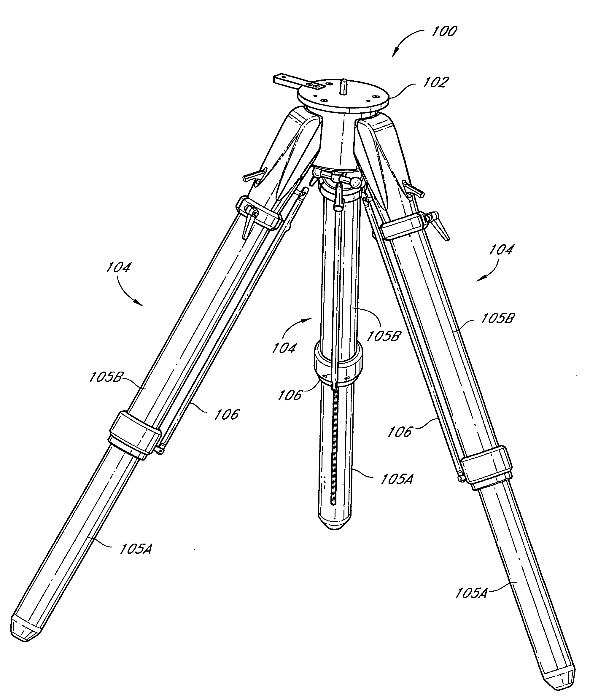
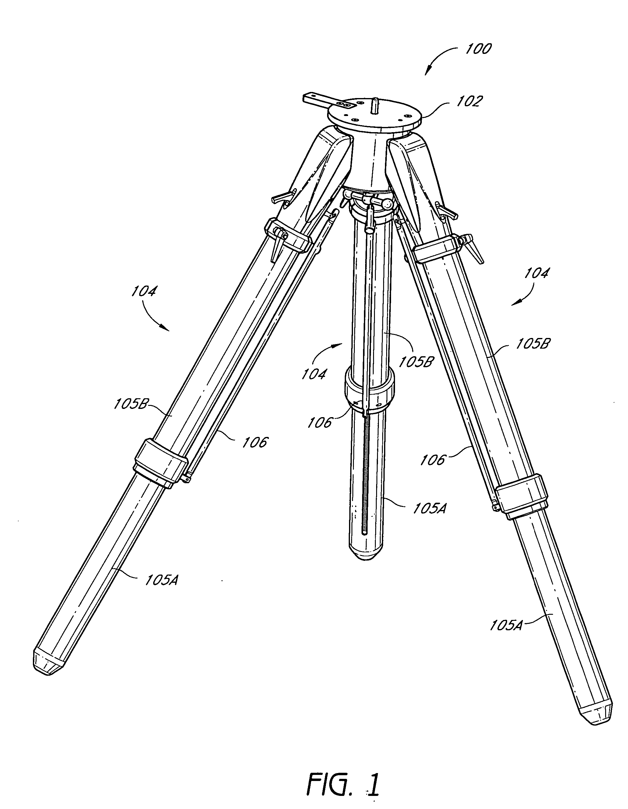
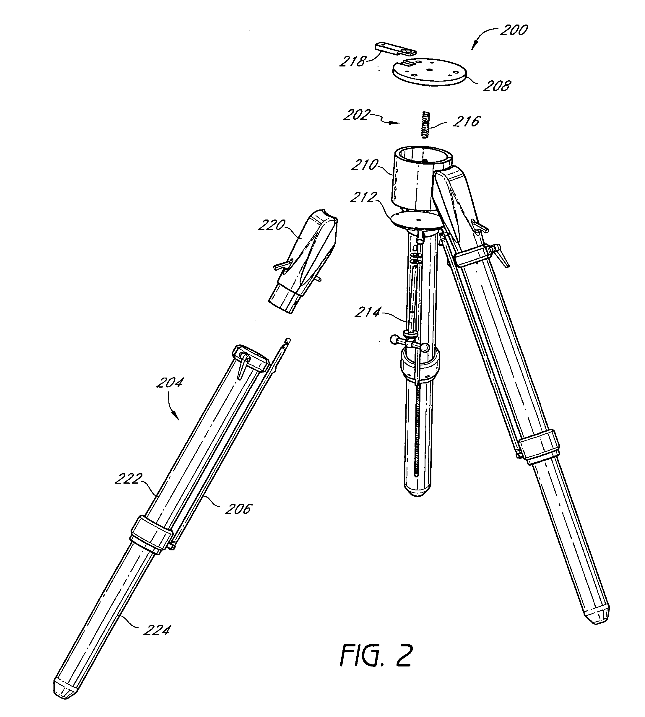
[0023] Embodiments of the disclosure include a stand, such as a tripod, for mounting often heavy and / or cumbersome equipment, such as, for example, optical equipment, survey equipment, or the like. The tripod advantageously includes a deployment assembly providing for straightforward and efficient deployment of the tripod legs in light of the difficulty anticipated with mounting the equipment. In an embodiment, the tripod provides for telescoping legs, each comprising an outer section and an inner section slidable within the outer section. Moreover each leg includes a rack and gear assembly, actionable by a trigger, to adjust the length of each telescoping leg. When the trigger, is in an engaging position, a ratchet lever catches or contacts at least one tooth of the rack gear such that the inner section is substantially immobilized with respect to the outer section. When the trigger moves to a disengaged position, the inner section may slide out of, or into, the outer section, ther...


PUM


Abstract

Embodiments of the disclosure include a stand, such as a tripod, including a deployment assembly for adjusting a height of the stand by, for example, adjusting a length of a telescoping tripod leg. In an embodiment, the deployment assembly adjusts the length of the tripod leg when the user actuates a control device, such as a trigger or a button. The control device may advantageously be located near the top of a tripod leg, which may facilitate leveling and / or heightening of the tripod. In addition, the deployment assembly may include a rack and gear assembly that controls relative movement of a lower leg segment with respect to an upper leg segment.

Description

RELATED APPLICATION [0001] The present application claims the benefit of priority under 35 U.S.C. § 119(e) of U.S. Provisional Patent Application No. 60 / 638,957 filed on Dec. 23, 2004, entitled “TRIPOD HAVING AUTOMATIC DEPLOYMENT,” the entirety of which is hereby incorporated herein by reference.BACKGROUND OF THE INVENTION [0002] 1. Field of the Invention [0003] The present disclosure relates to stands, such as stands for optical or photographic equipment. In particular, the present disclosure relates to systems and methods for adjusting the height of a stand. [0004] 2. Description of the Related Art [0005] Stands, such as, for example, tripods, are often used for supporting optical or photographic equipment in a stable manner and generally include multiple legs attached to a platform for supporting such equipment. Many conventional tripods include a leveling display that indicates to the user when the tripod is in a substantially level position. To properly set up the tripod, a use...

Claims


Application Information

Patent Timeline
Patent Type & Authority Applications(United States)
IPC IPC(8): F16M11/02
CPCF16M11/32F16M2200/024
Inventor WOOD, ROBERT A. IIIVALBUENA, RENE F.
Owner MEADE INSTRUMENTS
Why Eureka
Try Eureka