Self-locating device and program for executing self-locating method

a self-locating device and self-locating technology, applied in the direction of distance measurement, instruments, using reradiation, etc., can solve the problem of impossible self-locating

Inactive Publication Date: 2006-08-10
HITACHI LTD
View PDF6 Cites 39 Cited by
  • Summary
  • Abstract
  • Description
  • Claims
  • Application Information

AI Technical Summary

Benefits of technology

[0013] The invasion of a person or the like into the view makes possible identification of the device's own position and direction without having to recognize any specific marker.

Problems solved by technology

Therefore, if the prescribed landmarks fail to be detected or, even if detected, individual landmarks cannot be distinguished from one another, self-locating will be impossible.

Method used


Image

  • Self-locating device and program for executing self-locating method
  • Self-locating device and program for executing self-locating method
  • Self-locating device and program for executing self-locating method

Examples


Embodiment Construction

[0029] It is to be understood that the figures and descriptions of the present invention have been simplified to illustrate elements that are relevant for a clear understanding of the present invention, while eliminating, for the purpose of clarity, many other elements found in a self-locating device and method. Those of ordinary skill in the art may recognize that other elements and / or steps are desirable and / or required in implementing the present invention. However, because such elements and steps are well known in the art, and because they do not facilitate a better understanding of the present invention, a discussion of such elements and steps is not provided herein. The disclosure herein is directed to all such variations and modifications to such elements and methods known to those skilled in the art.

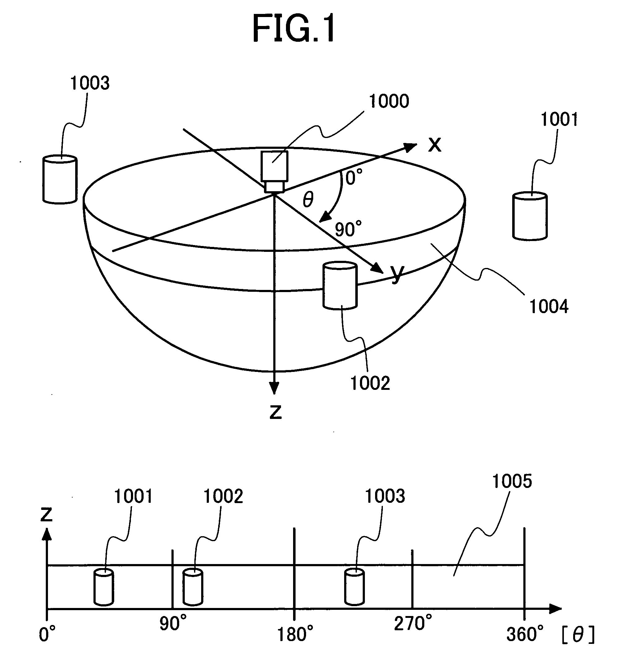
[0030]FIG. 1 illustrates the mode in which a self-locating process may be implemented according to an aspect of the present invention

[0031]FIG. 1 shows a state in which a wide-...


PUM


Abstract

A self-locating device that captures omni-directional camera images and determines its position and posture from the sensed images is disclosed. Omni-directional predicted images of a robot in a supposed moved position from an initial position are generated from omni-directional camera images that can be acquired when the robot is arranged in the initial position, and these predicted images and omni-directional images newly acquired when the robot has actually moved are matched with each other to detect the robot position and posture (direction).

Description

CLAIM OF PRIORITY [0001] The present application claims priority from Japanese application JP 2005-033772 filed on Feb. 10, 2005, the content of which is hereby incorporated by reference into this application. FIELD OF THE INVENTION [0002] The present invention relates to a self-locating method and device for taking omni-directional camera images and finding the position and posture of the device. BACKGROUND OF THE INVENTION [0003] A self-locating means intended for measuring the position of a apparatus is an indispensable constituent element of an autonomous mobile robot system. Supposing that such a robot is used within a building or in a space surrounded by shields, a method by which the robot locates itself according to markers within the field of view around would prove more useful than a configuration using the Global Positioning System (GPS) which is readily obstructed by shielding bodies. [0004] Typical methods of self-location using markers within the field of view around, ...

Claims


Application Information

Patent Timeline
Patent Type & Authority Applications(United States)
IPC IPC(8): G01C3/00G06K9/00
CPCG01C11/02G01S17/023G01S17/89G06K9/00664G06K9/3216G06K2009/3225G06T7/0044G06T7/74G01S17/86G06V20/10G06V10/245
Inventor KATO, MASAHIROKATO, TAKESHI
Owner HITACHI LTD
Why Eureka
Try Eureka