Electrical connector including snap-in lanyard

Inactive Publication Date: 2006-08-10
TE CONNECTIVITY CORP
View PDF16 Cites 2 Cited by
  • Summary
  • Abstract
  • Description
  • Claims
  • Application Information

AI Technical Summary

Benefits of technology

[0012] Desirably, the proximal aperture of each slider is configured and dimensioned to receive an engaging member of a respective leg of the extracting tab. It is envisioned that the engaging members projecti

Problems solved by technology

However, in densely packed arrays of receptacles, manipulation of the latching mechanism, for the plugs connected to substantially the centrally located recept

Method used


Image

  • Electrical connector including snap-in lanyard
  • Electrical connector including snap-in lanyard
  • Electrical connector including snap-in lanyard

Examples


Embodiment Construction

[0026] Embodiments of the presently disclosed connector will now be described in detail with reference to the drawing figures wherein like reference numerals identify similar or identical elements. As used herein and as is traditional, the term “distal” refers to that portion which is furthest from the user while the term “proximal” refers to that portion which is closest to the user. In addition, terms such as “above”, “below”, “forward”, “rearward”, etc. refer to the orientation of the figures or the direction of components and are simply used for convenience of description.

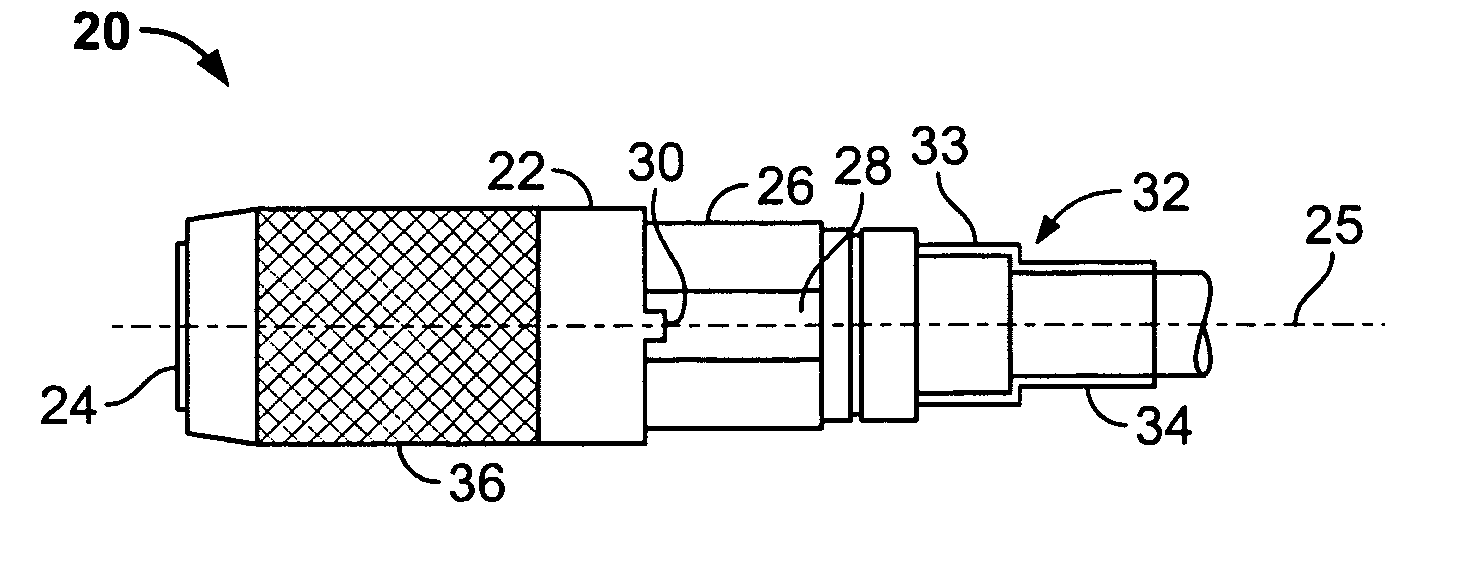
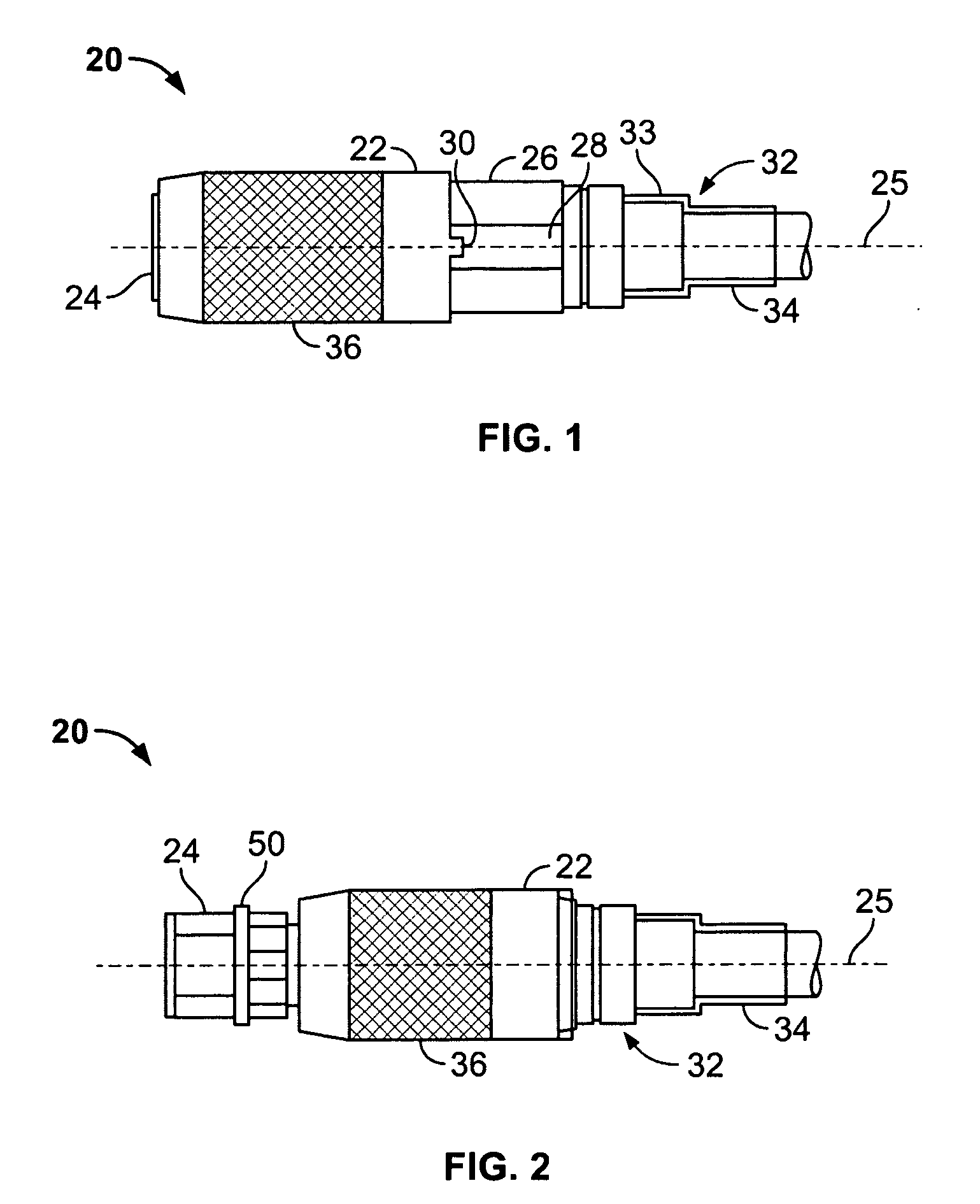
[0027] Referring initially to FIGS. 1-7, a connector (e.g., electrical connector, data connector, telephonic connector, etc.), to selective connection to a complementary receptacle (not shown), is generally designated as 100. Connector 100 includes a housing 102 for holding an end of a cable “C” therein, and a lanyard 130 for facilitating release and / or delatching of housing 102 from the corresponding receptac...


PUM


Abstract

A connector for electrical, telephonic and/or data transmission for selective engagement with a complementary receptacle, is provided. The connector includes a housing defining a pair of channels extending into slots at a rear surface of the housing and capable of supporting a contact member therein. The connector further includes a lanyard operatively associated with the housing. The lanyard includes locking and releasing arms slidably disposed within each channel of the housing, and an extracting tab selectively engageable with each locking and releasing arm. Additionally, the extracting tab includes a pair of legs insertable into a respective slot at the back of the housing. Each leg includes an engaging member projecting from an inner surface thereof for engaging a respective aperture formed in the slider. Desirably, the extracting tab is snap-fit connected to each locking and releasing arm.

Description

BACKGROUND [0001] 1. Technical Field [0002] The present disclosure relates to electrical, telephonic and / or data connectors and, more particularly, to electrical connectors including snap-in lanyards capable of locking and unlocking the electrical connector to a corresponding receptacle. [0003] 2. Background of Related Art [0004] Various latching mechanisms and lanyards have been developed and incorporated into electrical, data and / or telephonic cable connectors or plugs for mechanically connecting the plug to a corresponding complementary receptacle. Typically, in order to release the plug from the receptacle an individual must squeeze, depress or otherwise manipulate the latching mechanism in order to release the plug from the receptacle. [0005] However, in densely packed arrays of receptacles, manipulation of the latching mechanism, for the plugs connected to substantially the centrally located receptacles of the array, is greatly hindered and impaired as compared to manipulation...

Claims


Application Information

Patent Timeline
IPC IPC(8): H01R13/627
CPCH01R13/6275
Inventor MORANA, FRANCIS P.
Owner TE CONNECTIVITY CORP
Why Eureka
Try Eureka