Gear Transmission

Active Publication Date: 2022-04-07
KUBOTA LTD
View PDF0 Cites 0 Cited by
  • Summary
  • Abstract
  • Description
  • Claims
  • Application Information

AI Technical Summary

Benefits of technology

[0027]With the above-described arrangement, free rotation of the rotation support shaft against the ground-contact reaction force acting on the rear wheel is allowed by the transmission flexibility portion provided between the first transmission gear and the input shaft. Similarly, free rotation of the rotation support shaft against the ground-contact reaction force acting on t

Problems solved by technology

With this kind of conventional gear transmission, when a speed changing operation is to be effected, if respective end faces of the shift gear and the speed changing gear hit each other, ground-contact reaction force applied to the traveling device will be transmitted to the transmission mechanism to act on the rotation support shaft,

Method used


Image

  • Gear Transmission
  • Gear Transmission
  • Gear Transmission

Examples


Embodiment Construction

[0039]Next, an embodiment as an example of the present invention will be explained with reference to the accompanying drawings.

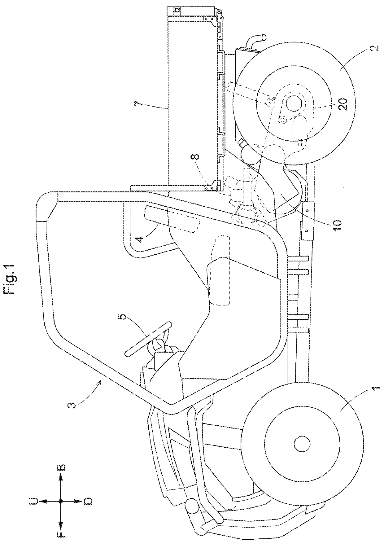
[0040]Incidentally, in the following explanation, with respect to a traveling vehicle body of a multiple-purpose vehicle, the direction of arrow F shown in FIG. 1 is defined as “vehicle body front side”, the direction of arrow B shown therein is defined as “vehicle body rear side”, the direction of arrow U shown therein is defined as “vehicle body upper side”, the direction of arrow D shown therein is defined as “vehicle body lower side”, the direction on the near (front) side of the plane of illustration is defined as “vehicle body left side”, and the direction on the far (back) side of the plane of illustration is defined as “vehicle body right side”, respectively.

[0041][General Arrangement of Multiple-Purpose Vehicle]

[0042]As shown in FIG. 1, the multiple-purpose vehicle includes a traveling vehicle body having a pair of steerable and drivable left and ri...


PUM


Abstract

A gear transmission having a speed changing section includes a speed changing gear for setting a speed stage and a shift gear slidably mounted on a rotation support shaft and operated to engage and disengage with the speed changing gear, the speed changing section configured to speed-change inputted power and to output the resultant power via the rotation support shaft. An arrangement is provided for facilitating engagement of the shift gear with the speed changing gear even when respective end faces of the shift gear and the speed changing gear hit each other. A transmission mechanism (20B) is provided for outputting power of a rotation support shaft (24) to a traveling device. The transmission mechanism (20B) has a transmission flexibility portion (80) which allows free rotation of the rotation support shaft (24) by a set rotation angle.

Description

CROSS-REFERENCE TO RELATED APPLICATION[0001]This application claims priority to Japanese Patent Application No. 2020-168721 filed Oct. 5, 2020, the disclosure of which is hereby incorporated by reference in its entirety.BACKGROUND OF THE INVENTION1. Field of the Invention[0002]The present invention relates to a gear transmission.2. Description of Related Art[0003]The gear transmission includes a speed changing section having a speed changing gear for setting a speed stage and a shift gear slidably mounted on a rotation support shaft and operated to be engaged / disengaged to / from the speed changing gear, the speed changing section configured to speed-change inputted power and to output the resultant power via the rotation support shaft, and a transmission mechanism configured to output the power of the rotation support shaft to a traveling device.[0004]An example of such gear transmission as above is known from e.g. Patent Document 1. The gear transmission disclosed in Patent Document...

Claims


Application Information

Patent Timeline
IPC IPC(8): B60K17/354F16H37/08
CPCB60K17/354F16H37/021F16H2702/04F16H37/0813F16H2200/0043F16H3/091F16H63/18F16H3/30B60K17/08F16H2702/00
Inventor YASUDA, TOSHIFUMIMORITA, YUSUKE
Owner KUBOTA LTD
Why Eureka
Try Eureka