Eureka AIR delivers breakthrough ideas for toughest innovation challenges, trusted by R&D personnel around the world.

Apparatus for forming high-impact transparent, distortion-free polymeric materials

a polymer material, distortion-free technology, applied in the field of polymer material forming, can solve the problems of reducing the service life of the transparent panel, less preferred applications, and not retaining as much impact strength as other polymeric materials, and achieve excellent optical properties and weatherability, outstanding resistance to effects, and high impact strength

Inactive Publication Date: 2007-10-25
CLEAR ARMOR LLC +1
View PDF37 Cites 0 Cited by
  • Summary
  • Abstract
  • Description
  • Claims
  • Application Information

AI Technical Summary

Benefits of technology

[0004] Traditionally, acrylic plastic is used to form such transparent panels. Acrylic plastic is noted for its excellent optical properties and weatherability, having outstanding resistance to the effects of sunlight and exposure to the elements over long periods of time. Subjected to long term exposure to the elements, acrylic plastic does not experience significant yellowing or any other significant changes in its physical properties. Acrylic plastic, however, does not retain as high an impact strength as do other polymeric materials and thus, are less preferred for applications where impact strength is of importance.
[0007] Accordingly, the present invention provides an apparatus for forming a polymeric material, such as polycarbonate. The present invention enables forming of a polycarbonate sheet without distorting the key visibility areas of the sheet. The apparatus of the present invention provides a forming mold including a first half having a bottom wall and a first side wall defining a first interior space and a first edge and a second half having a top wall and a second side wall defining a second interior space and a second edge. The first and second halves come together to clamp the peripheral edge portions of a sheet of polymeric material therebetween for forming the sheet whereby the sheet is vacuum drawn into one of the first and second interior spaces. A cooling mechanism is disposed within one of the first and second interior spaces and a sensing mechanism is attached to one of the first and second halves for sensing a draw depth of the sheet within one of the first and second interior spaces. The first edge is preferably contoured for defining a final edge contour of the sheet and the second edge correspondingly contoured for facilitating engagement of the first and second halves. Further, the first edge is preferably beveled and the second edge correspondingly beveled for facilitating engagement of the first and second halves.

Problems solved by technology

Acrylic plastic, however, does not retain as high an impact strength as do other polymeric materials and thus, are less preferred for applications where impact strength is of importance.
However, the transparent panels, whether produced using acrylic plastic or polycarbonate, include a hard protective coating to prevent scratching, abrasions or other markings that would reduce the service life of the transparent panel.
However, the upper and lower surfaces of a polycarbonate sheet are not as hard and therefore, when heated, may be distorted upon contact during the forming process.
For this reason, the use of traditional molds, which directly contact the upper and lower surfaces of the polymeric sheet, are not desirable for forming polycarbonate sheets.
Traditional molds have increased potential for distorting the surfaces of the polycarbonate sheet, thus producing an increased number of rejected panels and driving up production costs.

Method used


Image

  • Apparatus for forming high-impact transparent, distortion-free polymeric materials
  • Apparatus for forming high-impact transparent, distortion-free polymeric materials
  • Apparatus for forming high-impact transparent, distortion-free polymeric materials

Examples


Embodiment Construction

[0021] The following description of the preferred embodiments is merely exemplary in nature and is in no way intended to limit the invention, its application, or uses.

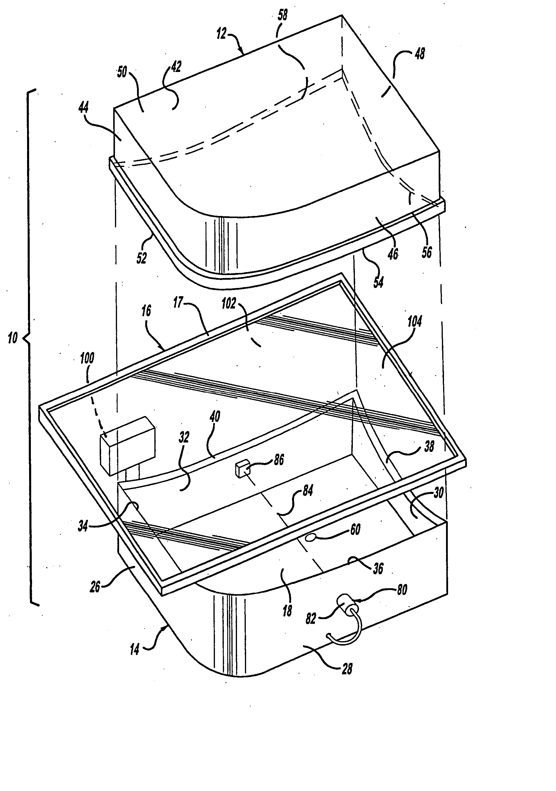
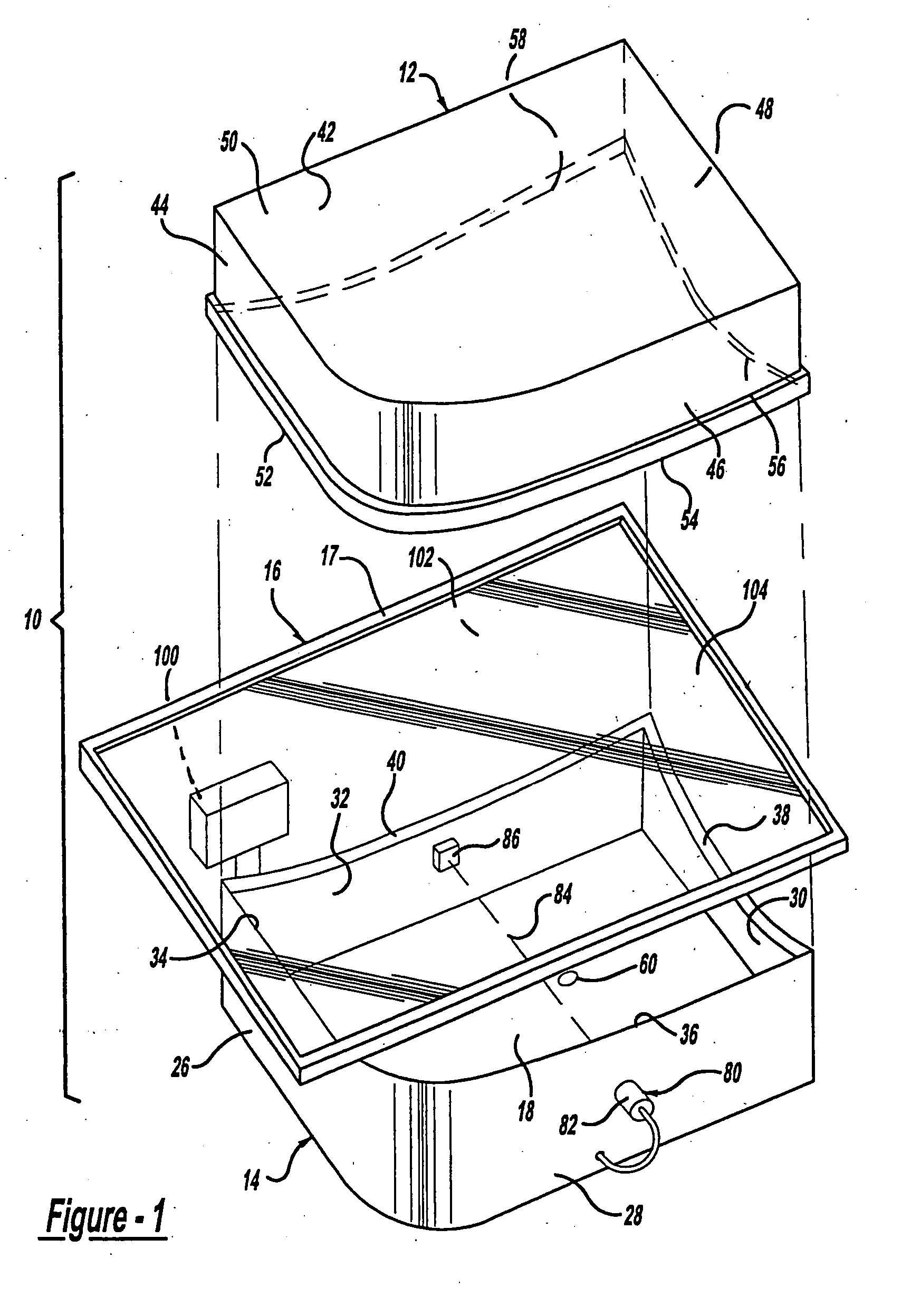
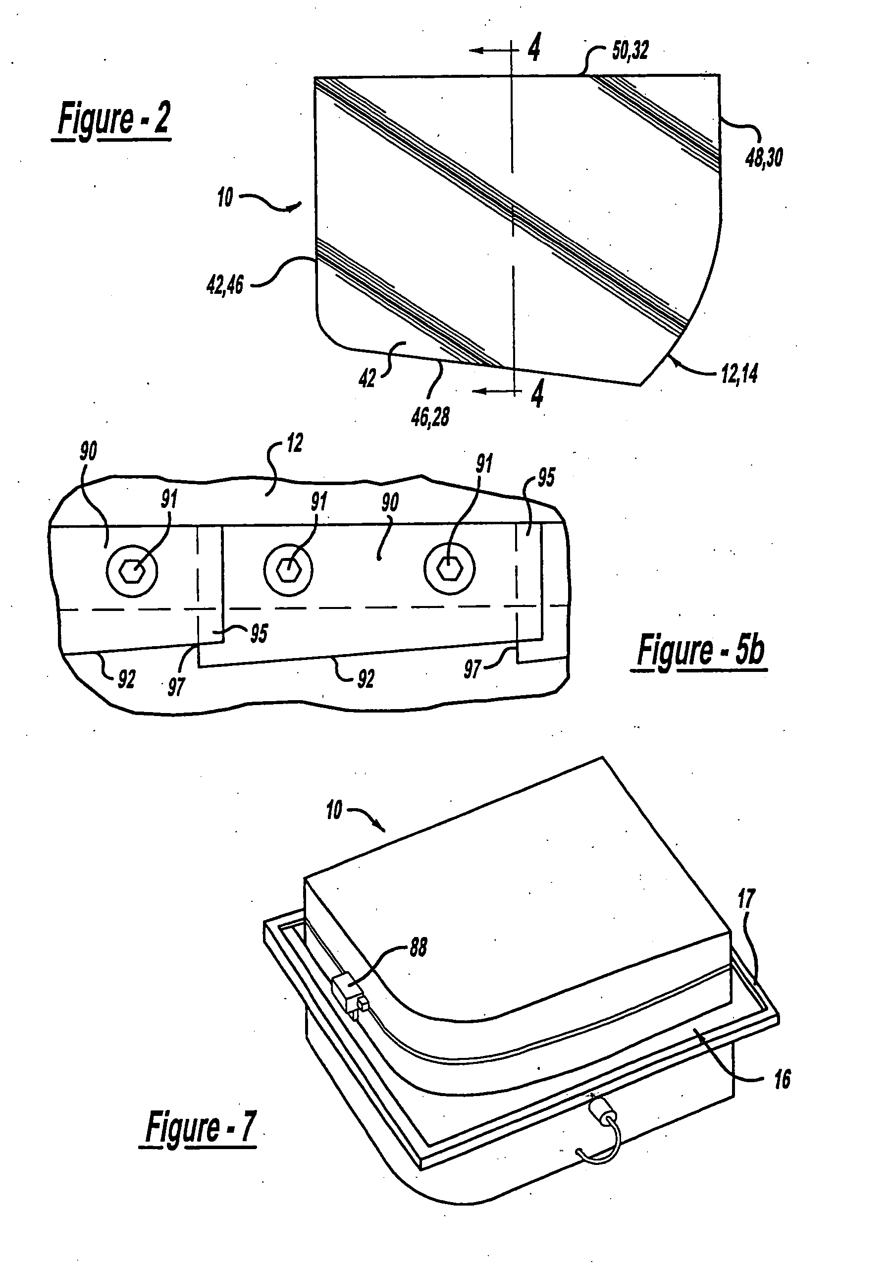
[0022] With reference to the Figures, there is shown a forming mold 10 including upper and lower halves 12, 14 that come together to form a heated sheet of polymeric material 16 therebetween. The sheet 16 is preferably an optical quality polycarbonate material and is retained within a rigid frame 17 having a length and width somewhat greater than that of the upper and lower halves 12, 14, and that clamps about the complete peripheral edge of the sheet 16. Edges of the upper and lower halves 12, 14 are contoured to define a desired end form for peripheral edges of the sheet 16. A vacuum is created within an interior space 18 of the lower half 14 for drawing the sheet 16 downward, thereby forming the sheet 16 as defined by the contoured edges of the upper and lower halves 12, 14. The drawing process ensues until the she...


PUM

PropertyMeasurementUnit
Temperatureaaaaaaaaaa
Pressureaaaaaaaaaa
Sizeaaaaaaaaaa

Abstract

A method and apparatus are provided for forming a sheet of polymeric material, such as polycarbonate. A forming mold is provided having halves that engage for forming a heated sheet therebetween. Each of the halves defines an interior cavity having a peripheral edge. The sheet is retained between the peripheral edges of the halves and a vacuum is generated within one of the cavities for drawing the sheet therein, whereby a sensing mechanism detects a draw depth for initiating a cooling mechanism to cool the sheet to a temperature below a glass transition temperature of the material. A series of retention mechanisms are provided about the peripheral edge of one of the halves, for biasing the sheet into engagement with the peripheral edge of the opposing half. A trimming mechanism is further provided for trimming the perimeter of the sheet to a desired form.

Description

CROSS-REFERENCE TO RELATED APPLICATIONS [0001] This application is a divisional of U.S. Ser. No. 10 / 300,329, filed Nov. 20, 2002, which is a divisional of U.S. Ser. No. 09 / 928,827, filed Aug. 13, 2001 (now U.S. Pat. No. 6,733,714), which applications are herein expressly incorporated by reference.BACKGROUND AND SUMMARY OF THE INVENTION [0002] The present invention relates generally to forming polymeric materials and more particularly to a method and apparatus for forming polymeric materials. [0003] Polymeric materials are used in a wide variety of applications. Typically, polymeric materials are used to manufacture transparent panels such as windows or windshields for various applications including aircraft, automobiles, motorcycles, boats and the like. Such applications, especially those for aircraft, require an extremely clear, undistorted, transparent panel, which is resistive to scratching and impact in order to afford the pilot a clear view of the surroundings. [0004] Tradition...

Claims


Application Information

Patent Timeline
IPC IPC(8): B29C51/10B29C35/16B29C51/00B29C51/04B29C51/08B29C51/26B29C51/32B29C51/42B29C51/46
CPCB29C51/008B29K2069/00B29C51/082B29C51/10B29C51/262B29C51/32B29C51/421B29C51/427B29C51/428B29C51/46B29C2035/1658B29C2791/006B29C2791/007B29C2793/00B29K2033/08B29C51/04Y10T428/31507
Inventor OAKEY, EDWIN J.TINNEY, RODNEY M.
Owner CLEAR ARMOR LLC
Why Eureka
Eureka Blog
Learn More