Method of manufacturing light guide plate, light guide plate, backlight unit with the light guide plate and display apparatus having the same

Active Publication Date: 2008-12-18
CITIZEN ELECTRONICS CO LTD
View PDF7 Cites 39 Cited by
  • Summary
  • Abstract
  • Description
  • Claims
  • Application Information

AI Technical Summary

Benefits of technology

[0009]An object of the present invention is

Problems solved by technology

The above-described conventional techniques, however, still have the following problems to be solved.
Examination of luminance uniformity at the light exiting surface of the prototype, however, often r

Method used


Image

  • Method of manufacturing light guide plate, light guide plate, backlight unit with the light guide plate and display apparatus having the same
  • Method of manufacturing light guide plate, light guide plate, backlight unit with the light guide plate and display apparatus having the same
  • Method of manufacturing light guide plate, light guide plate, backlight unit with the light guide plate and display apparatus having the same

Examples


Embodiment Construction

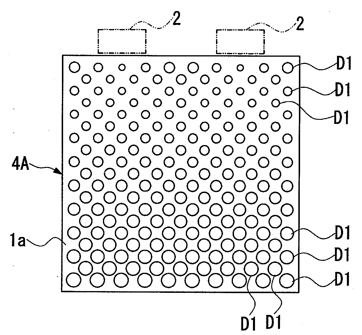
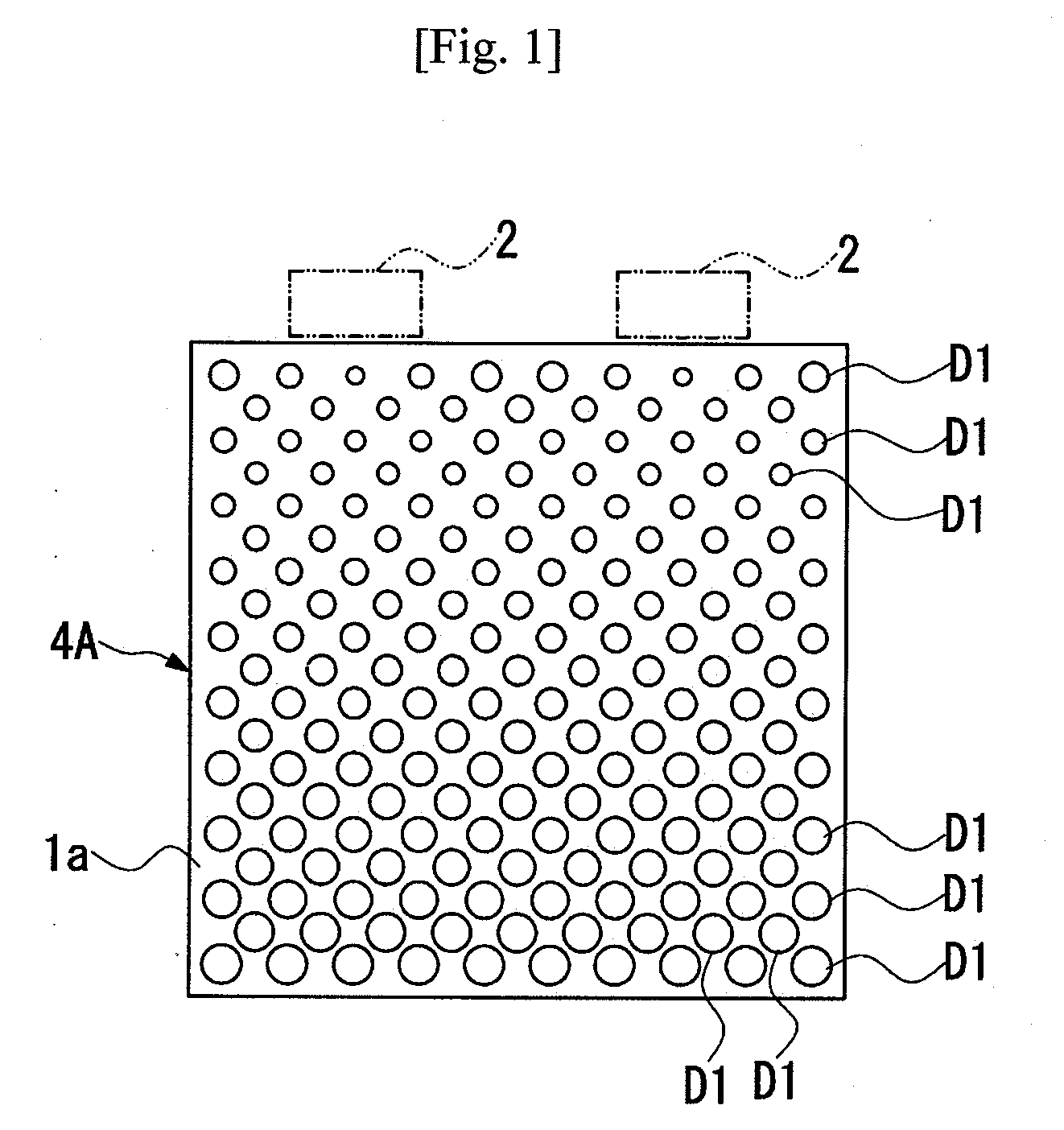
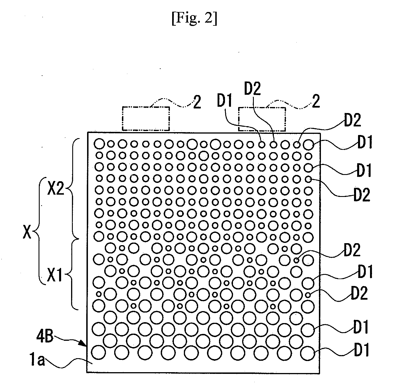
[0032]A light guide plate producing method according to an embodiment of the present invention is to produce a light guide plate 4, as shown in FIG. 5, which is used in a backlight unit 5 of a liquid crystal display apparatus 10. The light guide plate 4 has a light exiting surface 1b, which is an upper surface as viewed in FIG. 5, a light reflecting surface 1a, which is a lower surface, and a light entrance surface that receives light from a light source 2. The light reflecting surface 1a has a multiplicity of light reflective dots formed thereon to diffuse and reflect light entering the light guide plate 4 so as to allow the light to exit from the light exiting surface 1b uniformly. In the following embodiment, the light reflective dots are formed as short hemispherical or columnar projections projecting from the light reflecting surface 1a (see FIGS. 7 and 8). The light reflective dots, however, may be recesses and may be formed by printing.

[0033]In the light guide plate producing...


PUM

PropertyMeasurementUnit
Diameteraaaaaaaaaa
Sizeaaaaaaaaaa
Densityaaaaaaaaaa

Abstract

A method of producing an edge-light type light guide plate having a light exiting surface and a light reflecting surface having light reflective dots formed thereon in a scattered fashion. The method includes (a) producing a first prototype of the light guide plate having primary dots formed on the light reflecting surface, (b) examining optical characteristics of the first prototype relating to light exiting from the light exiting surface thereof, and (c) producing a second prototype of the lightguide plate when the examined first prototype exhibits unsatisfactory optical characteristics. The second prototype has primary dots that are the same as the primary dots of the first prototype in size and distribution, and secondary dots arranged between the primary dots in at least part of the light reflecting surface. The steps (b) and (c) are repeated until a prototype is produced which exhibits satisfactory optical characteristics.

Description

[0001]This application claims priority under 35 U.S.C. §119 to Japanese Patent application No. JP2007-158073 filed on Jun. 14, 2007, the entire contents of which are hereby incorporated by reference.TECHNICAL FIELD[0002]The present invention relates to light guide plates for use in display apparatus and the like.RELATED ART[0003]Liquid crystal display apparatus have been widely used in mobile phones, personal digital assistants (PDAs), automatic teller machines (ATMs), displays of personal computers, etc. These liquid crystal display apparatus employ a backlight unit that applies light to a liquid crystal display panel from the back thereof to enhance a luminance of the display screen.[0004]The backlight unit uses a light guide plate that receives light from a light source such as LEDs (light-emitting diodes) and that applies the light toward the entire back surface of the liquid crystal display panel. This type of light guide plate is demanded to apply light to the liquid crystal d...

Claims


Application Information

Patent Timeline
IPC IPC(8): F21V7/04G01N21/00G02B6/00
CPCG02B6/0043Y10T428/24802G02B6/0065G02B6/0061
Inventor KATSUMATA, TOSHINOBU
Owner CITIZEN ELECTRONICS CO LTD
Why Eureka
Try Eureka