Optical configuration for imaging-type optical encoders

a technology of optical encoder and optical configuration, applied in the field of optical or photoelectric encoder, can solve the problems of measurement error, change in reflected light angle, unstable signal characteristics, etc., and achieve the effects of reducing optical aberration, small diameter, and simple form

Active Publication Date: 2007-01-25
MITUTOYO CORP
View PDF12 Cites 41 Cited by
  • Summary
  • Abstract
  • Description
  • Claims
  • Application Information

AI Technical Summary

Benefits of technology

[0040] In accordance with another aspect of the invention, in various embodiments which include a lens and an aperture located at the focal point of the lens, a second lens may be positioned between the aperture and the light receiving element. In one exemplary embodiment the second lens is located nominally symmetrically to the other lens about the plane of the aperture, and has optical characteristics that are similar or identical to the other lens. Thus, the second lens tends to compensate or eliminate optical aberrations induced by the first lens. In various exemplary embodiments, such an arrangement is used with economical lenses that are of particularly small diameter and simple form, in order to provide superior optical characteristics and an accurate image despite the low cost, small size and simplicity of such lenses.
[0041] In accordance with a separate aspect of the invention, various embodiments of the encoder readhead are constructed in a particularly economical, accurate, and compact manner.
[0042] Hence, various embodiments of the invention overcome the disadvantages of prior art imaging-type optical displacement sensing devices that use a relatively simple optical arrangement including a lens to provide an image of a scale pattern. Various embodiments include a telecentric aperture designed specifically to provide a diffraction-limited optical system and a desired combination of encoder operating characteristics, in order to provide measurements at an improved level of accuracy, resolution, and robustness by the use of particularly simple and economical elements.

Problems solved by technology

Therefore, as shown in FIG. 19, when there is waviness at the surface of the main scale 40, a measurement error may result from a change in a reflected angle of light.
However, the signals provided by an encoder according to the '519 patent are suitable only for very crude levels of measurement signal interpolation.
In addition, various characteristics of the signals are not stable with respect to various potential misalignments and gap variations between the encoder readhead and scale.
Thus, an encoder according to the '519 patent cannot provide robust signals suitable for significant levels of measurement signal interpolation.
Thus, their resolution and accuracy are relatively crude.

Method used


Image

  • Optical configuration for imaging-type optical encoders
  • Optical configuration for imaging-type optical encoders
  • Optical configuration for imaging-type optical encoders

Examples


first embodiment

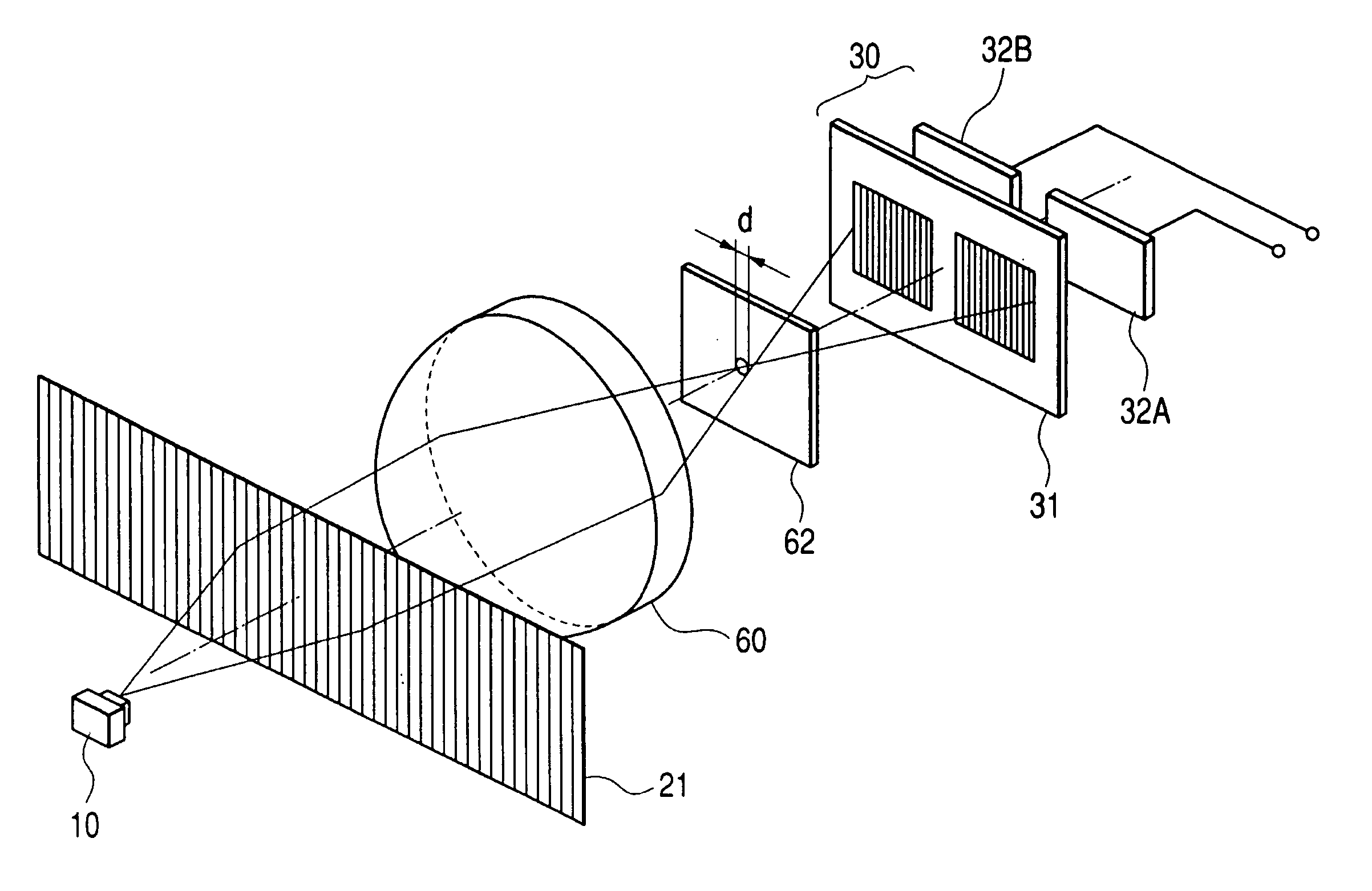
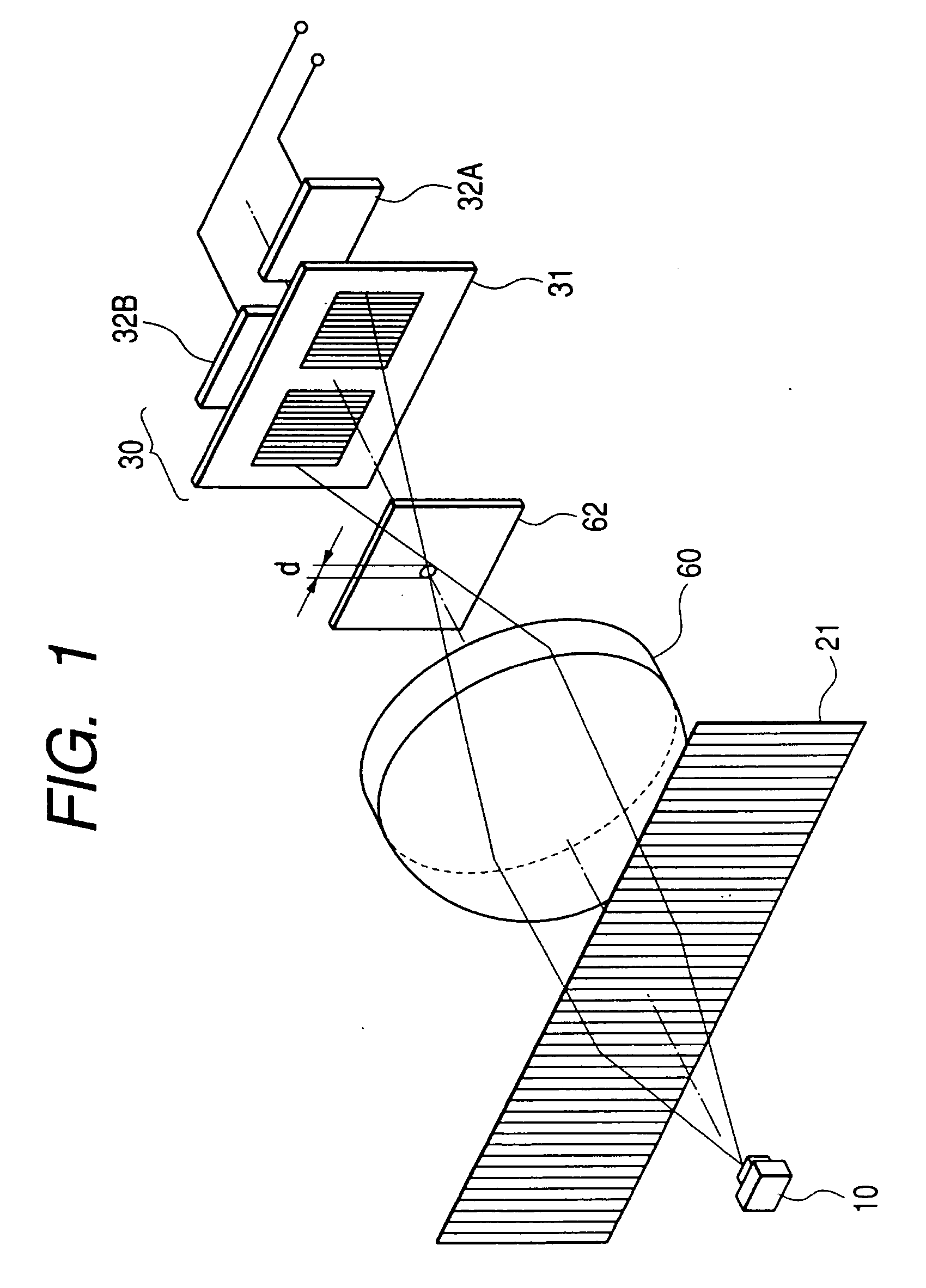
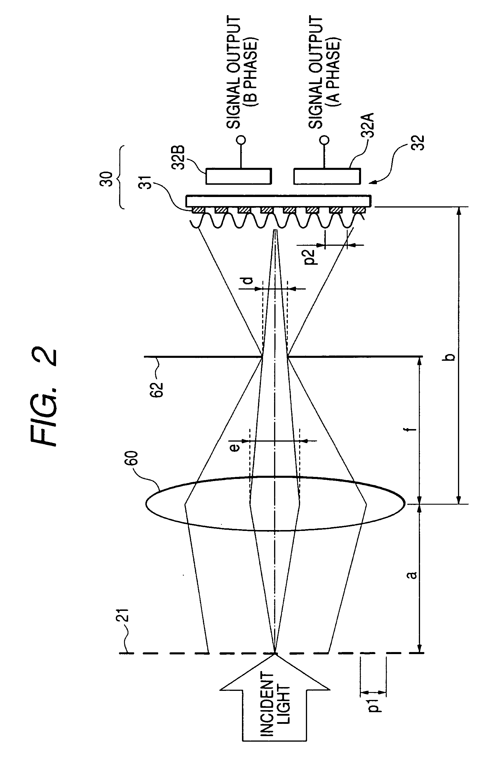
[0082] According to the present invention, in a transmission-type photoelectric encoder similar to that in the related art shown in FIG. 15, as shown in FIG. 1 (perspective view) and FIG. 2 (optical path view), a light source 10 is provided. Further, a lens 60 and an aperture 62 are inserted between the first grating 21 of the main scale 20 and the light receiving portion 30, and a magnification of an image is set by adjusting distances a and b between the lens 60 and the first grating 21 and between the lens 60 and the index grating pattern 31, respectively.

[0083] According to the first embodiment, light emitted from the light source 10 passes through the first grating 21 of the main scale 20 and is incident on the lens 60. Only light emitted from the lens 60 along an optical axis passing through the aperture 62 provided at a focal point of the lens 60 reaches the index grating pattern 31 to form an image of the first grating 21.

[0084] Here, the magnification is calculated from a ...

second embodiment

[0094] Further, as a second embodiment, the light receiving portion 30 can be replaced by the light receiving element array similar to that in FIG. 16, as shown in FIG. 3.

[0095] Although there is only one optical axis according to the first and the second embodiments, as a third and a fourth embodiment, an explanation will be given of a structure for detection by an optical system comprising a plurality of optical axes using a lens array and an aperture array as follows.

[0096] According to the first and the second embodiments described above, the focal length of the lens is 3 mm and, therefore, a distance connecting the main scale, the lens, and the index grating pattern falls in a range of 12 through 13.5 mm. In order to achieve further small-sized formation, the focal length of the lens needs to be reduced.

[0097] However, when the focal length of the lens is reduced, in the case of a general lens that is readily obtainable, a diameter thereof is reduced. (FIG. 4 shows a list of ...

fourth embodiment

[0099]FIG. 6 shows a fourth embodiment in which the light receiving portion 30 is changed to the light receiving element array 33.


PUM


Abstract

A displacement measuring device including a scale, and an optical readhead including an index pattern and a light receiving element is provided. A bright/dark pattern arising from a scale grating is detected by the readhead to measure displacement. In various embodiments, a magnification of the pattern is adjusted by the spacing between at least a lens element, aperture element, and detection plane of the readhead. An aperture can be designed to provide a diffraction-limited telecentric imaging configuration that filters an image of the scale grating to provide a sinusoidal intensity pattern that supports highly interpolated measurements. An aperture dimension, selected in relation to the grating pitch and other parameters, can provide a desirable combination of readhead operating characteristics including one or more of a desired depth of field; degree of spatial filtering; and optical signal power.

Description

FIELD OF THE INVENTION [0001] The present invention relates to optical or photoelectric encoders that sense the displacement of a periodic scale pattern. BACKGROUND OF THE INVENTION [0002] In the related art, a transmission-type photoelectric encoder as shown in FIG. 15 has been used. The transmission-type photoelectric encoder as shown in FIG. 15 includes a light source 10, a collimator lens 12, a transmission-type main scale 20, and a light receiving portion 30. The collimator lens 12 forms the light emitted from the light source 10 into parallel rays. The transmission-type main scale 20 has a first grating 21 having a predetermined pitch P at a surface (lower face in the drawing) thereof. The light receiving portion 30 consists of an index grating 31 having a predetermined pitch Q and a light receiving element 32. [0003] In the transmission-type photoelectric encoder of FIG. 15, since the index grating 31 and the light receiving element 32 are formed as individual parts, they nee...

Claims


Application Information

Patent Timeline
Patent Type & Authority Applications(United States)
IPC IPC(8): G01D5/34G01D5/347G01D5/36G02B13/22
CPCG01D5/00G01D5/38G01D5/36G01D5/34715
Inventor SHIMOMURA, TOSHITAKANIHOMMORI, SHINGOMIZUTANI, MIYAKO
Owner MITUTOYO CORP
Why Eureka
Try Eureka