A booster assembly

a booster and assembly technology, applied in the field of booster assemblies, can solve the problems of safety risks for mine personnel, safety risks are also compounded, and achieve the effect of facilitating facilitating the engagement of the booster assembly

Inactive Publication Date: 2021-09-02
NEWCREST MINING
View PDF0 Cites 0 Cited by
  • Summary
  • Abstract
  • Description
  • Claims
  • Application Information

AI Technical Summary

Benefits of technology

[0019]The booster and the spool may have complementary formations that allow the spool to receive and locate the booster and thereby seat the booster on the spool.
[0023]The booster casing may have an engagement feature, such as a collar, that facilitates engagement of the booster with a delivery assembly, for example that forms part of an initiation system vehicle, for transporting the booster assembly to a delivery position directly above the hole.
[0024]The spool may comprise a spool casing having an engagement feature, such as a collar, that facilitates engagement of the booster assembly with the delivery assembly for transporting the booster assembly to an intermediate transfer position proximate the delivery position directly above the hole. With this arrangement, in use, the delivery assembly can transport the booster to the loading position directly above the hole, with the spool and the stake remaining at the intermediate transfer position.
[0053]The internal guide may include an outer surface that has a diameter that is marginally less than a diameter of an internal wall of the tube and, in use, contacts the inner wall and facilitates sliding movement of the guide in the tube.

Problems solved by technology

There are safety risks for the mine personnel when on a pit floor.
The safety risks are compounded when mining operations are carried out in extreme conditions, such as in mines located in very hot and in very cold regions.
The safety risks are also compounded when mining in and around pits where there is geothermal activity and the surface of the pit floor is hot and unstable and the pit temperature increases with depth.
When mining in these pits, by way of example there can be unpredictable geysers in drilled holes, with hot water / steam being projected upwardly.

Method used


Image

  • A booster assembly
  • A booster assembly
  • A booster assembly

Examples


Embodiment Construction

[0079]The embodiments of the booster assembly of the invention are described in the context of use with embodiments of initiation system vehicle (“ISV”) of the invention of the co-pending International application mentioned above.

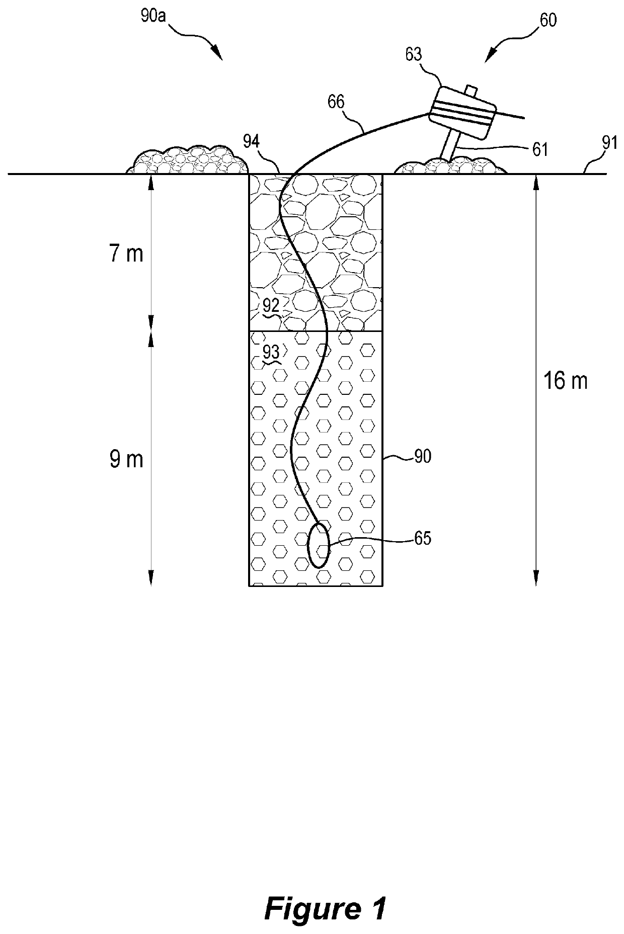
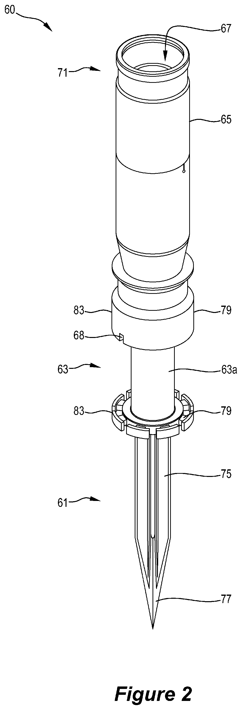
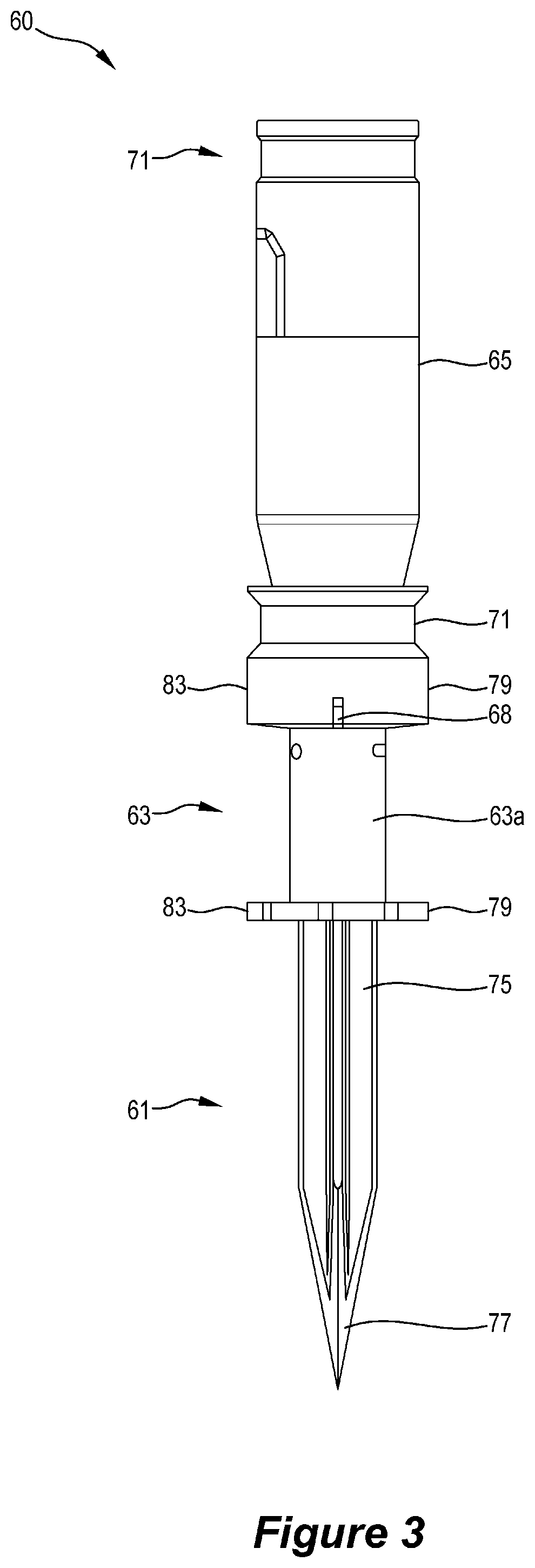
[0080]FIG. 1 illustrates in very schematic form a booster 65 of an embodiment of a booster assembly 60 in accordance with the invention, such as shown in FIGS. 2 to 6, and the other Figures after the initiation system vehicle (“ISV”)—not shown in the Figures but described in more detail below—has positioned the booster 65 in a drilled hole 90 in a pit floor 91 at a selected operative depth submerged in an emulsion explosive 93 in the hole 90, with the hole 90 being stemmed and a detonator cord 66 extending from the stemmed hole 90a.

[0081]As shown in FIG. 1, the drilled hole 90 is filled via the opening 94 to a depth of 9 m with an explosive emulsion 93 rated to operate in high temperature pits, such as produced by Dyna Nobel, the booster 65 is submerged in...


PUM


Abstract

A booster assembly (60) for use in a drill and blast operation comprises in co-axial alignment: (a) a booster (65) for initiating an explosion of an explosives material in a hole (90) in a pit floor (91) as part of a drill and blast operation, (b) a spool (63) and a detonation cord (66) wrapped around the spool in a storage position outside the hole and connected to the spool and to the booster, and (b) a stake (61). The spool allows the detonation cord to be unwound from the spool as the booster is moved from the storage position to an operative depth in the hole and the spool remains in the storage position. The stake is provided for locating the spool in the pit floor proximate the hole after the booster is at the operative depth in the hole.

Description

TECHNICAL FIELD[0001]The invention relates to a booster assembly for use in drill and blast operations.BACKGROUND[0002]The drill and blast process used on many mining sites involves a number of operations that are carried out by mine personnel on a pit floor.[0003]There are safety risks for the mine personnel when on a pit floor. The safety risks are compounded when mining operations are carried out in extreme conditions, such as in mines located in very hot and in very cold regions. The safety risks are also compounded when mining in and around pits where there is geothermal activity and the surface of the pit floor is hot and unstable and the pit temperature increases with depth. When mining in these pits, by way of example there can be unpredictable geysers in drilled holes, with hot water / steam being projected upwardly.[0004]The applicant is involved in a research and development project to minimise the above-described safety risks.[0005]As part of the project, the inventors of ...

Claims


Application Information

Patent Timeline
Patent Type & Authority Applications(United States)
IPC IPC(8): F42D1/22F42B3/10F42B3/26F42B3/02F42D3/04
CPCF42D1/22F42B3/10F42D3/04F42B3/02F42B3/26F42D1/02F42D1/04
Inventor OLIVER, JAMES THOMASSPRAGUE, ANTHONY JAMES
Owner NEWCREST MINING
Why Eureka
Try Eureka