Eureka AIR delivers breakthrough ideas for toughest innovation challenges, trusted by R&D personnel around the world.

Truss and joist brace

Inactive Publication Date: 2003-10-02
HUDSON JIMMY
View PDF33 Cites 1 Cited by
  • Summary
  • Abstract
  • Description
  • Claims
  • Application Information

AI Technical Summary

Benefits of technology

[0036] One feature of the present invention is that the framing engaging leg includes a series of spaced apertures. These spaced apertures have the advantage of enabling the construction personnel to place the frame members at properly spaced intervals from each other. Additionally, the spaced cut-outs also serve as braces for the frame members, to impart lateral stability to the frame members.
[0039] The deck engaging leg of the present invention holds the decking in place at a fixed position upon the roof, thereby facilitating the engagement of the deck member to the frame members by the carpenter.
[0041] A further feature of the present invention is that the frame engaging member can include a series of ear members that can be moved to extend in a plane generally perpendicular to the plane of the frame engaging member. The ears can be positioned adjacent to a side surface of a truss member. A nail or other fastening member can be driven through the ear member, into the truss member for fixedly coupling the spacer / bracer to the truss member. This feature has the advantage of fixedly positioning the spacer / bracer to the truss member. Additionally, by strengthening the bond between the spacer / bracer and the truss member, the overall strength of the truss system, and the roof, floor and / or wall it supports can also be strengthened significantly.

Problems solved by technology

One difficulty that occurs with trusses, is stabilizing the truss units and bracing them after the truss units are attached to the supporting walls, and before decking is applied to the upper surface of the truss units, to form the floor, or roof (as appropriate).
The dimensions set forth create a device that usually has very little lateral stability when not supported, or not joined to other truss units.
As such, the truss units are subject to toppling over on their sides when they are supported only at their base by the attachment to a supporting wall.
Two significant difficulties exist when assembling an array of truss units into a truss system for a building.
The first difficulty relates to obtaining the proper spacing between truss units.
A second difficulty relates to bracing the truss units to provide the truss units with lateral stability.
However, the truss units do not have great lateral stability before the decking is attached to their top surfaces.
Another difficulty that exists in connection with the construction of a roof relates to the placement of the decking on the upper surfaces of the inclined members of a truss unit (in a roof system), or the upper surfaces of the joist members of a floor joist system.
One difficulty with attaching the plywood decking to the truss unit is that it is often difficult to properly position the decking material in a desired spot on the truss unit, and to maintain that decking in its proper location between the time that the decking material is laid upon the truss system, and that time when the decking material is secured to the truss unit such as by nailing the decking to the truss unit.
Maintaining the proper position of a decking member is especially problematic when the decking member is being attached to a pitched roof, as the force of gravity upon the decking member will tend to cause it to slide down the truss.
This potential for movement of a decking member also increases the difficulty of aligning adjacent members together, so that adjacent decking members are "squared" with each other, so that their opposing edges align, to reduce the sizes of the cracks therebetween.

Method used


Image

  • Truss and joist brace
  • Truss and joist brace
  • Truss and joist brace

Examples


embodiment 100

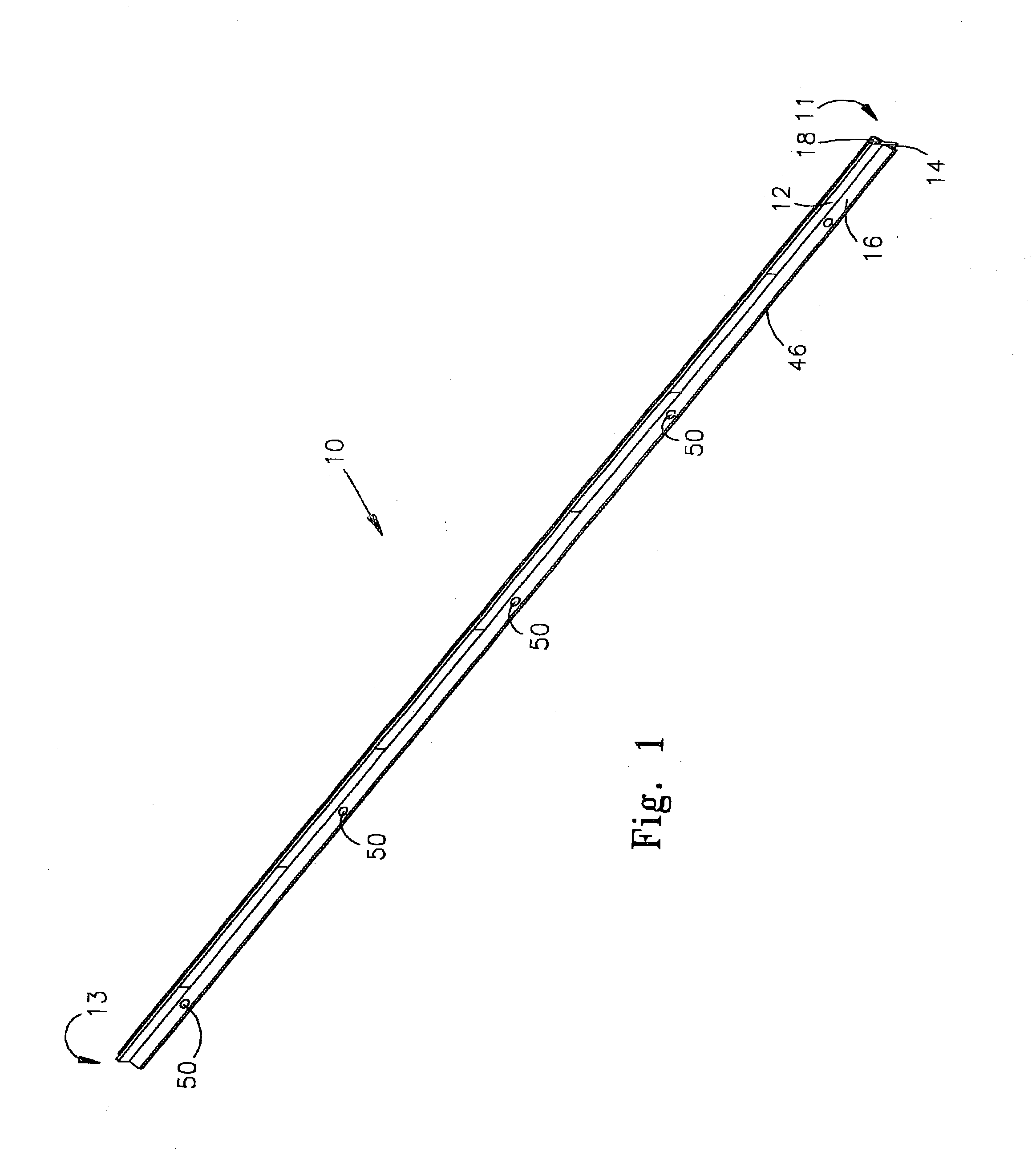
[0075] T-shaped spacer 100 includes a first end 102 and a second end 104, along with a vertically extending, frame engaging leg 106, and a wing 108 comprised of first 110 and second 112 wing portions. First wing portion 110 is generally similar in its position and lateral extent to the first wing of spacer 10, and also to second wing portion 112. The first and second wing portions 110, 112 are co-planar, and are disposed in a plane generally perpendicular to the plane in which the vertical leg 106 is disposed. As best shown in FIG. 9, the T-Brace embodiment 100, in cross section is formed from a single elongated strip that is rolled and bent to a first laterally extending wing portion 110 that is generally one sheet thick except for the double sheet thickness rolled end flange 111.

[0076] A hemicylindrical stiffening rib 113 is formed to extend the length of the T-Brace 100. Second laterally extending wing portion 112 is generally a similar mirror image of first wing portion 110, and...

embodiment 400

[0088] Turning now to FIGS. 13 and 14, an alternate embodiment 400 is shown that is particularly well adapted at receiving I-Joist such as are commonly used in floor systems. I-Joist Brace 440 is generally similar in configuration to T-Braces 100 and 300, except that it includes a multi-part break away tab that is designed to accommodate I-Joists 440 having laterally extending legs 446 of varying widths. Similar to the T-Braces discussed above, the break away tabs forming the cut out portions 406 can be arrayed in more than one series to accommodate different spacing regimes. Additionally, the break away tabs can be configured similarly to the break away tab 350 of brace 300, insofar as they can be hingedly coupled to the vertically extending leg 404 of the T-Brace 400, rather than being complete "break away" tabs, as is discussed in connection with the embodiments shown in FIGS. 13 and 14.

[0089] T-Brace 400 includes a laterally extending wing 402 that is generally similar to the T-...


PUM


Abstract

A brace system is provided for bracing at least two frame members of a multi-frame member containing frame system of a building. The brace system includes an elongated brace having a length sufficient to extend between at least two frame members. The brace includes a generally vertically extending frame engaging leg having at least three cut-out portions therein, the cut-out portions being disposed at predetermined intervals for receiving frame members. First and second wing members extend generally perpendicular to the frame engaging leg and are positioned for resting on an upper surface of a frame member. A deck engaging leg extends in a plane generally perpendicular to the wing members, and includes a deck engaging surface positioned for serving as a rest for decking members.

Description

I PRIORITY CLAIM[0001] This application claims priority to provisional patent application filed Mar. 29, 2002, Ser. No. 60 / 369,094.II. TECHNICAL FIELD OF THE INVENTION[0002] The present invention relates to devices for use in construction of a building, and more particularly to a spacer / bracer for use in connection with a truss system of the type typically used in the roof, floor or walls of a building.III BACKGROUND OF THE INVENTION[0003] An integral part of a building is the frame of the building. The frame of buildings, and especially residential buildings, usually consists of an ordered array of elongated frame members. The frame members are disposed in a spaced parallel relationship, and commonly consist of a plurality of wood or steel members, such as 2".times.4", 2".times.6" or 2".times.10" frame members, the length of which is usually several feet or great. The particular orientation, length, and type of frame members used depend upon the particular type and size of the buil...

Claims


Application Information

Patent Timeline
IPC IPC(8): E04B1/26E04C3/02
CPCE04B1/26E04C2003/026E04B1/2604
Inventor HUDSON, JIMMY
Owner HUDSON JIMMY
Why Eureka
Eureka Blog
Learn More