Auxiliary power coupler

Active Publication Date: 2009-04-02
FCA US
View PDF7 Cites 2 Cited by
  • Summary
  • Abstract
  • Description
  • Claims
  • Application Information

AI Technical Summary

Benefits of technology

[0006]In accordance with another aspect of the present invention, the foregoing clasps may be spaced on the housing to engage electrical system terminals so as to facilitate a one-handed engagement of the coupler with the vehicle electrical system. In accordance with yet another aspect of the present invention

Problems solved by technology

However, there are situations when power for a vehicle electrical system must be provided from some external source other than the vehicle's battery.
Additionally,

Method used


Image

  • Auxiliary power coupler
  • Auxiliary power coupler
  • Auxiliary power coupler

Examples


Embodiment Construction

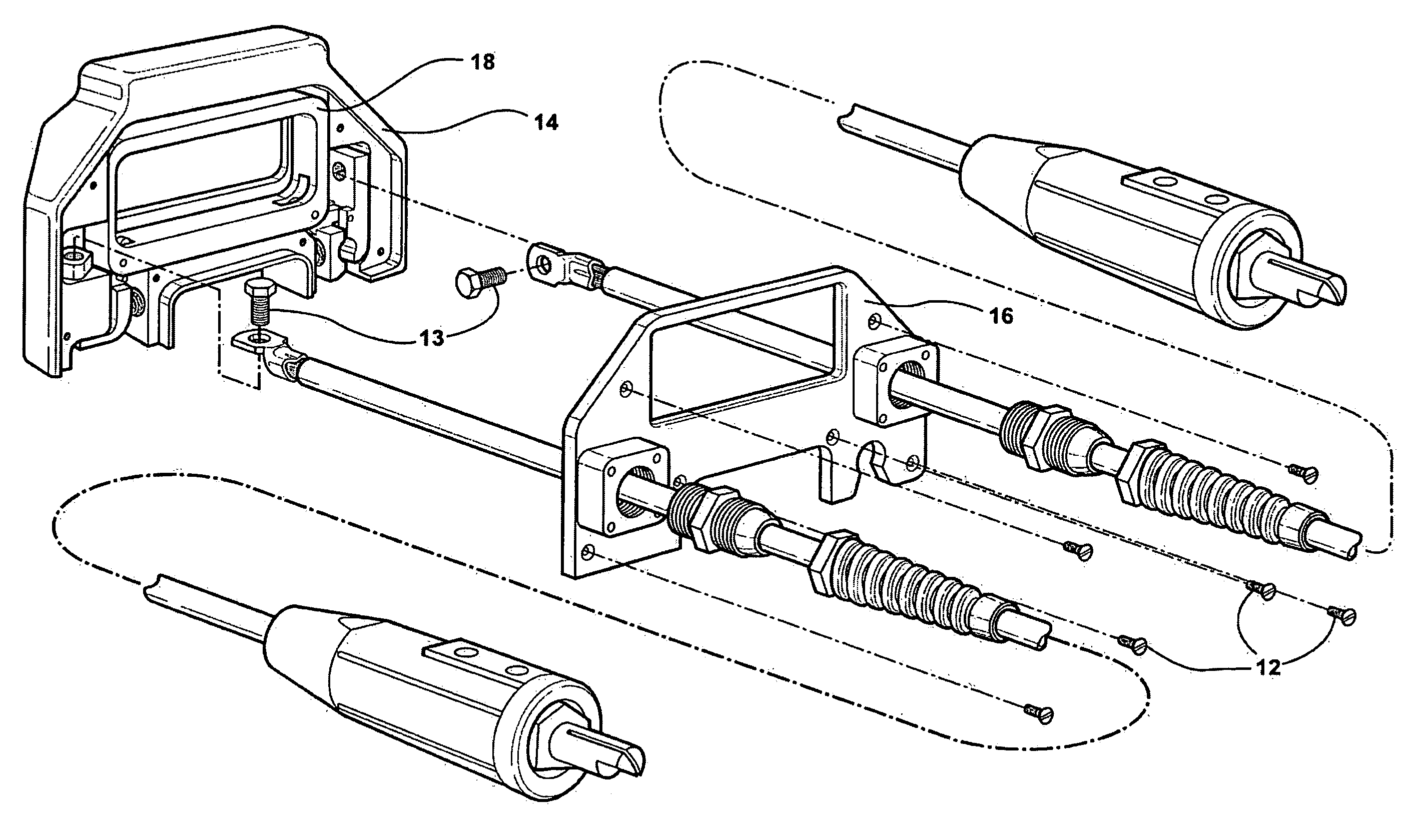
[0014]In general the present invention is directed to a power coupler for connecting a remote auxiliary power source to a vehicle electrical system. More specifically, the present invention is a power coupler which is particularly well-suited for use on a vehicle assembly-line to connect a remote auxiliary power source to vehicle electrical terminals to power up a specific vehicle system to complete its construction. The present invention, however, may also be applied to power-up a vehicle electrical system from an auxiliary power source, e.g. another vehicle, in the event that the subject vehicle's battery loses charge after leaving the assembly-line.

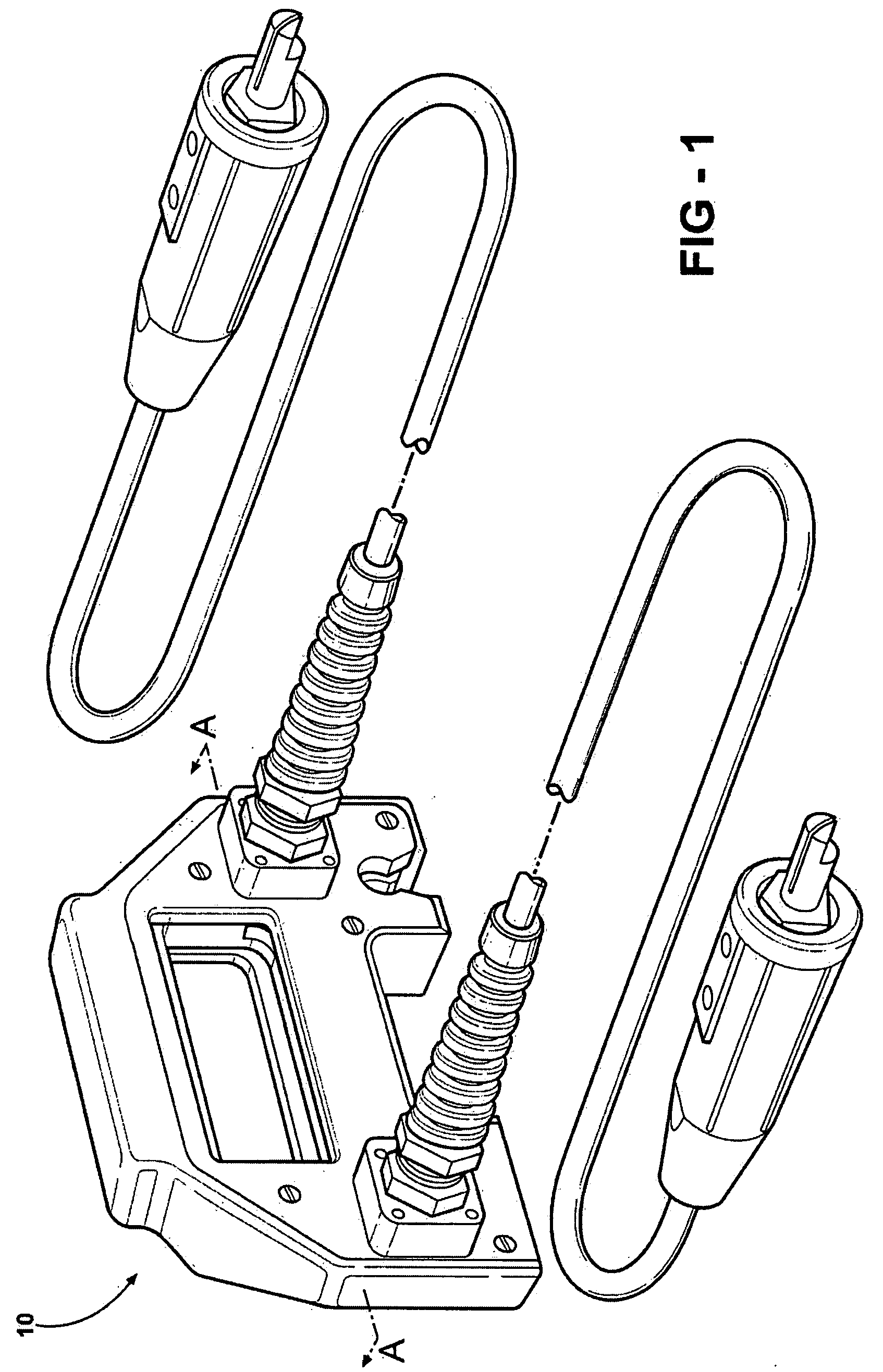
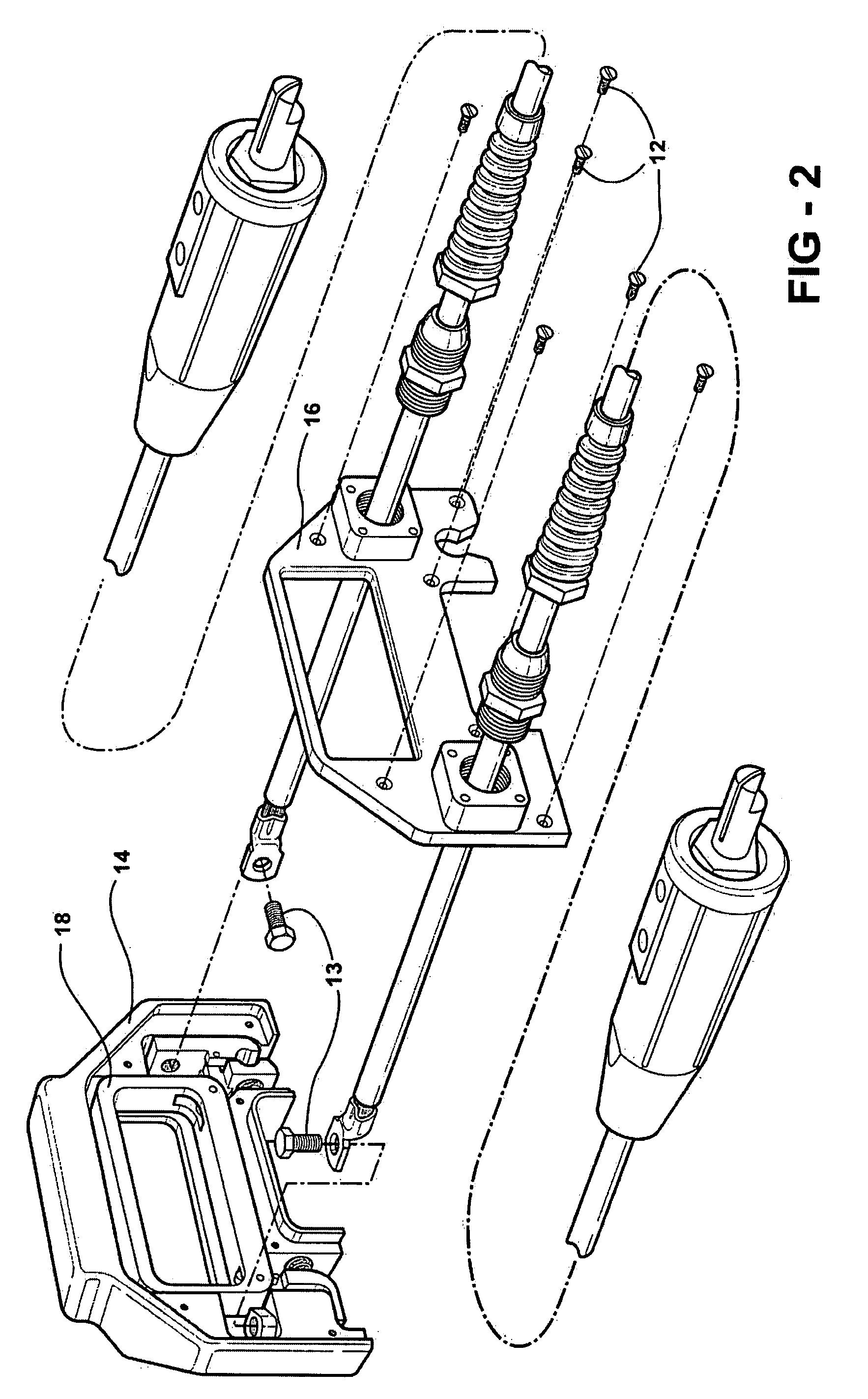
[0015]Referring now to the drawings in which like elements of the invention are identified with identical reference numerals throughout, FIG. 1 denotes a coupler 10. As best seen from FIG. 2, coupler 10 is held together by screw 12, however any suitable fastener may be used. Coupler 10 includes a housing 14, a cover 16, and an actuator...


PUM


Abstract

A coupler for connection of a power source to a vehicle electrical system. The coupler includes a housing arranged to be grasped by an operator, and an actuator arranged to be accessible when the housing is grasped. A plurality of electrically-conductive clasps are arranged on the housing and employ a mechanism to bias the clasps in a closed position for attachment to the vehicle electrical system. A linkage connecting the actuator to the claps is further provided to simultaneously open the clasps when the actuator is activated.

Description

FIELD OF THE INVENTION[0001]The present invention relates to a coupler for connecting a remote auxiliary power source to a vehicle electrical system.BACKGROUND OF THE INVENTION[0002]A vehicle's electrical system is designed to be powered by an on-board battery. However, there are situations when power for a vehicle electrical system must be provided from some external source other than the vehicle's battery. For example, during initial vehicle build in an assembly-plant, as the vehicle progresses through various assembly-line stages when the battery is disconnected from its electrical system for safety considerations, an external power source is required to systematically power-up a specific vehicle system to complete its construction. Additionally, after a vehicle leaves the assembly-line its battery may lose charge, and a jump start may be required from an auxiliary power source, e.g. from another vehicle.[0003]Connecting means or devices typically used for this purpose are jumper...

Claims


Application Information

Patent Timeline
IPC IPC(8): H01R4/48
CPCH01R11/281H01R2201/26H01R13/6392
Inventor SKRZYNIARZ, JEFFREYMISTALSKI, LAWRENCEMCCLESKEY, TINA
Owner FCA US
Why Eureka
Try Eureka