

Drain valve for freight container
- Summary
- Abstract
- Description
- Claims
- Application Information
AI Technical Summary
Benefits of technology
Problems solved by technology
Method used
Image

Examples
Example
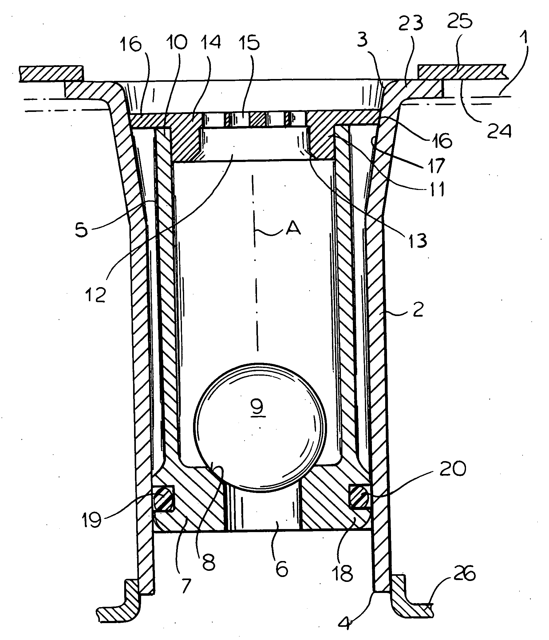
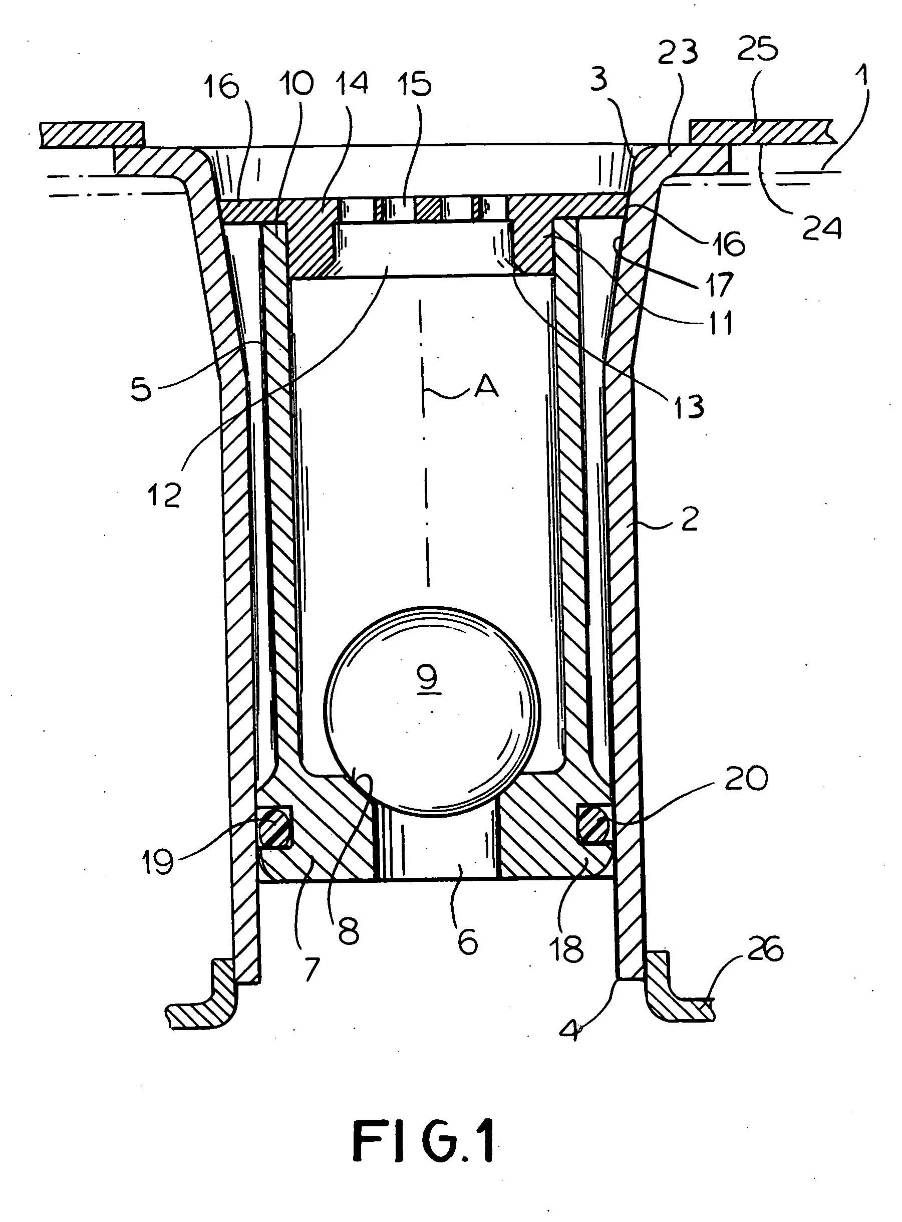
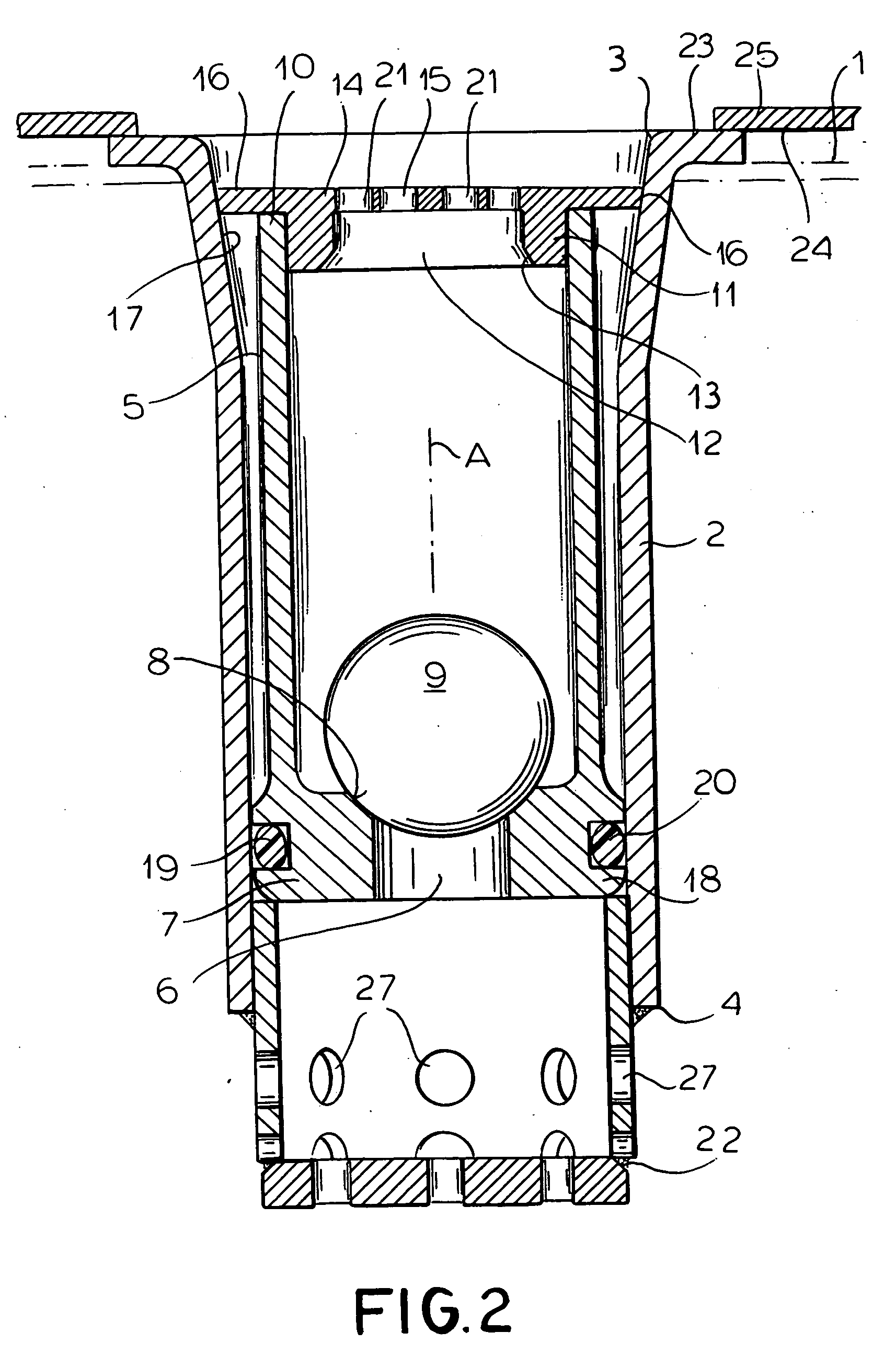
[0017] As seem in FIG. 1 a drain valve according to the invention is fitted in a freight-container floor 1 having a horizontal top plate or skin 25 and a horizontal bottom plate or skin 26, between which is normally provided unillustrated insulation. The container having the floor 1 must normally be protected against the entry or exit of air or gases from its interior, must also be able to automatically drain in the event water or another liquid gets on the floor, and must keep out any water or liquid it might be standing in or on.
[0018] The valve comprises an outer housing tube 2 centered on a normally vertical axis A and having an upwardly open and flared frustoconical upper and 3 and a cylindrical and downwardly open lower end 4. An inner housing tube 5 is coaxially received in the outer tube 2 and has a lower wall or floor 7 formed with cylindrical central throughgoing lower hole or aperture 6. A frustoconical lower seat 8 formed at the upper side of the hole 6 fits with a circ...
PUM
 Abstract
Description
Claims
Application Information