Device for bottling beverages

Active Publication Date: 2014-06-24
KRONES AG
View PDF25 Cites 1 Cited by
  • Summary
  • Abstract
  • Description
  • Claims
  • Application Information

AI Technical Summary

Benefits of technology

[0022]Preferably, the bypass line has a smaller flow cross-section than the valve device in an open state. As a result, the flow rate do

Problems solved by technology

Under certain circumstances however, for example if the containers that are to be filled break or if the containers exhibit a crack or a non-optimally cooled base after blowing, excessively high flow rates may occur in the

Method used


Image

  • Device for bottling beverages
  • Device for bottling beverages

Examples


Embodiment Construction

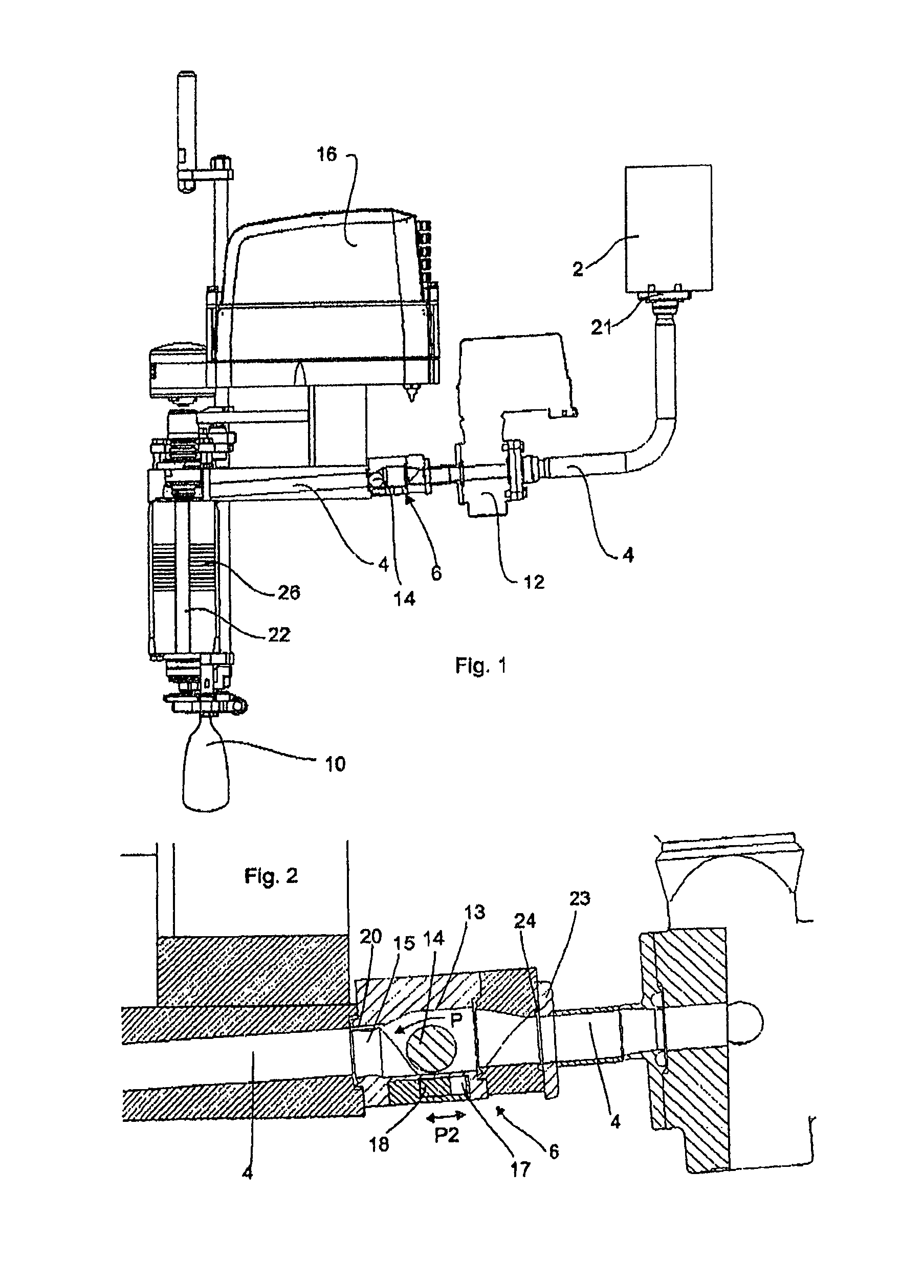
[0027]FIG. 1 shows an overall view of a device according to the invention for filling containers. Here, reference 2 denotes a storage container (shown only schematically), from which the medium or the beverage is filled into the containers (not shown) via a transport line 4. Reference 22 denotes a supply line, via which a gaseous medium such as carbon dioxide or nitrogen for example is supplied to the container 10. The beverage that is to be bottled is passed around this air line 22. For this purpose, a bellows-type seal 26 (shown only schematically) is provided, which controls the supply of the beverage into the containers.

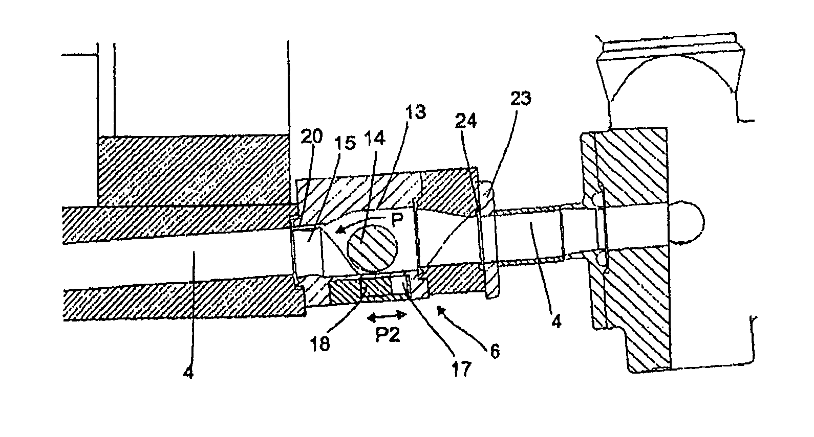
[0028]In the event of faults, for example in the event of bottles breaking, it sometimes happens that the beverage that is to be bottled flows through this valve device 24 at high pressure and possibly damages the latter.

[0029]In order to avoid such damage, a valve device 6, which is embodied as a non-return valve, is provided inside the transport line 4. Referen...


PUM

PropertyMeasurementUnit
Flow rateaaaaaaaaaa

Abstract

A device for filling containers, includes a storage container in which a fluid that is to be bottled in the containers can be accommodated, a filling device which fills the fluid into the containers, and a transport line for transporting the fluid from the storage container to the filling device. A valve device is arranged in the transport line between the storage container and the filling device, which valve device automatically switches between an open and a closed state depending on a flow rate of the fluid within the transport line.

Description

FIELD OF THE INVENTION[0001]The present invention relates to a device for bottling beverages. Many devices such as this are known from the prior art. In these devices, starting from a storage container such as an annular vessel, a beverage that is to be bottled is bottled into the beverages via a supply line and a filling device.BACKGROUND OF THE INVENTION[0002]DE 103 43 281 A1 discloses a method and a device for producing and bottling oxygen-enriched fluids. This device comprises a filling member with a fluid valve, and also a nitrogen-filled chamber, wherein a through-connection for flushing and / or pre-charging the container with nitrogen can be established between the nitrogen-filled chamber and a container attached to the filling member.[0003]DE 201 20 014 U1 describes a rotary filling machine for filling bottles. This rotary filling machine comprises a rotor which is rotatable about a vertical axis and on which a plurality of filling valves are arranged. The filling valves are ...

Claims


Application Information

Patent Timeline
IPC IPC(8): B67C3/02F16K31/08F16K15/04
CPCY10T137/7869B67C3/28Y10T137/791F16K31/08B67C3/007
Inventor POESCHL, STEFANMEINZINGER, RUPERT
Owner KRONES AG
Why Eureka
Try Eureka