Icing detector

a detector and detector technology, applied in the direction of instruments, fluid pressure measurement, transportation and packaging, etc., can solve the problems of aircraft performance and control, loss of lift and/or control, and thus of aircra

Active Publication Date: 2020-07-02
ISRAEL AEROSPACE IND
View PDF2 Cites 1 Cited by
  • Summary
  • Abstract
  • Description
  • Claims
  • Application Information

AI Technical Summary

Problems solved by technology

Ice buildup on aircraft, in particular on their aerodynamic lift and control surfaces, can seriously affect the perf

Method used


Image

  • Icing detector
  • Icing detector
  • Icing detector

Examples


Embodiment Construction

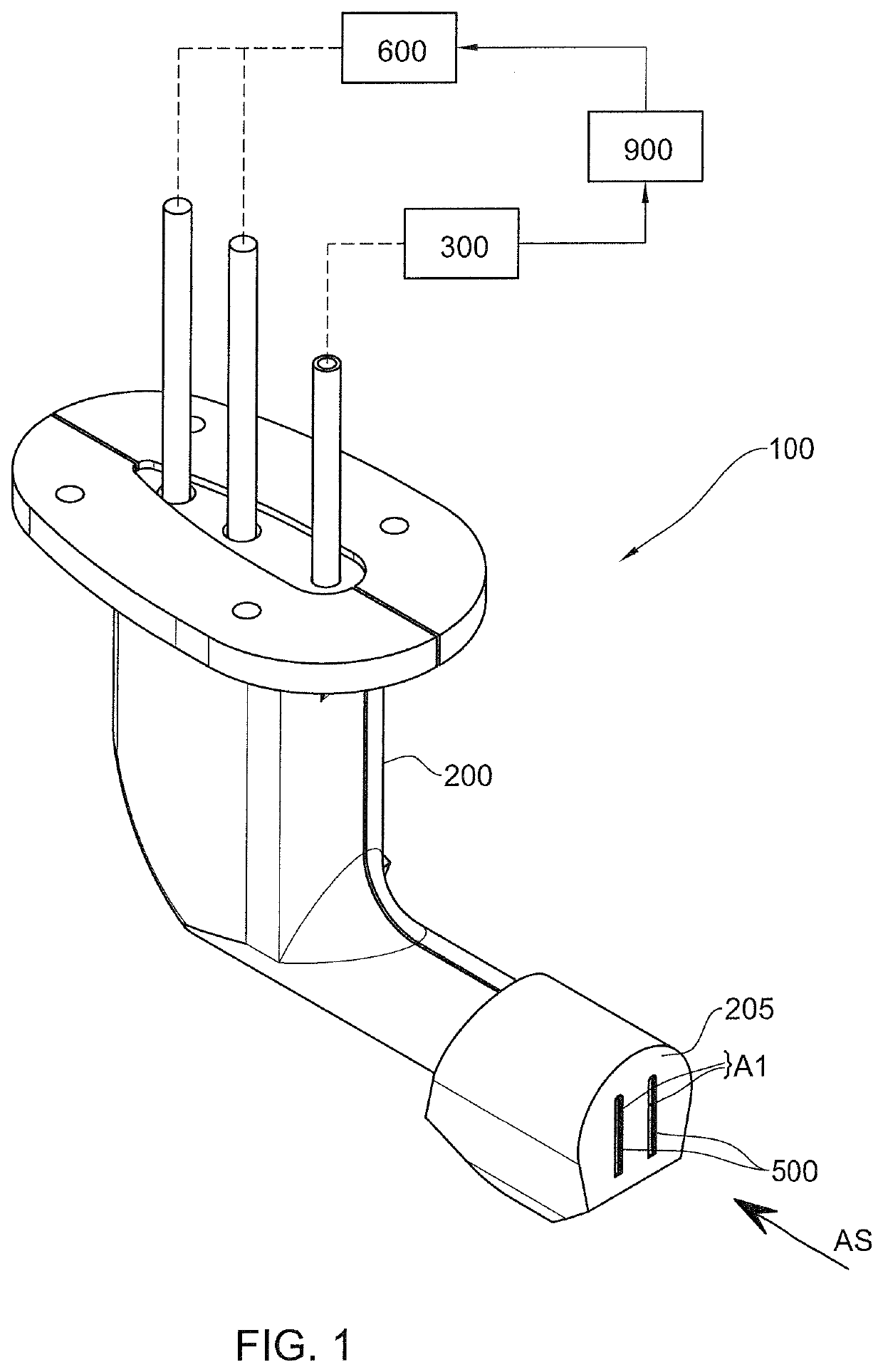
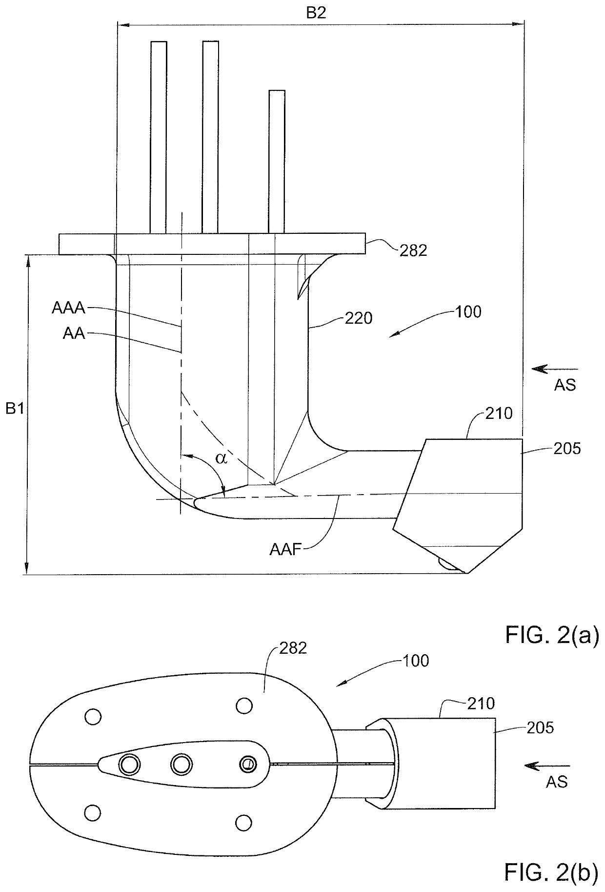
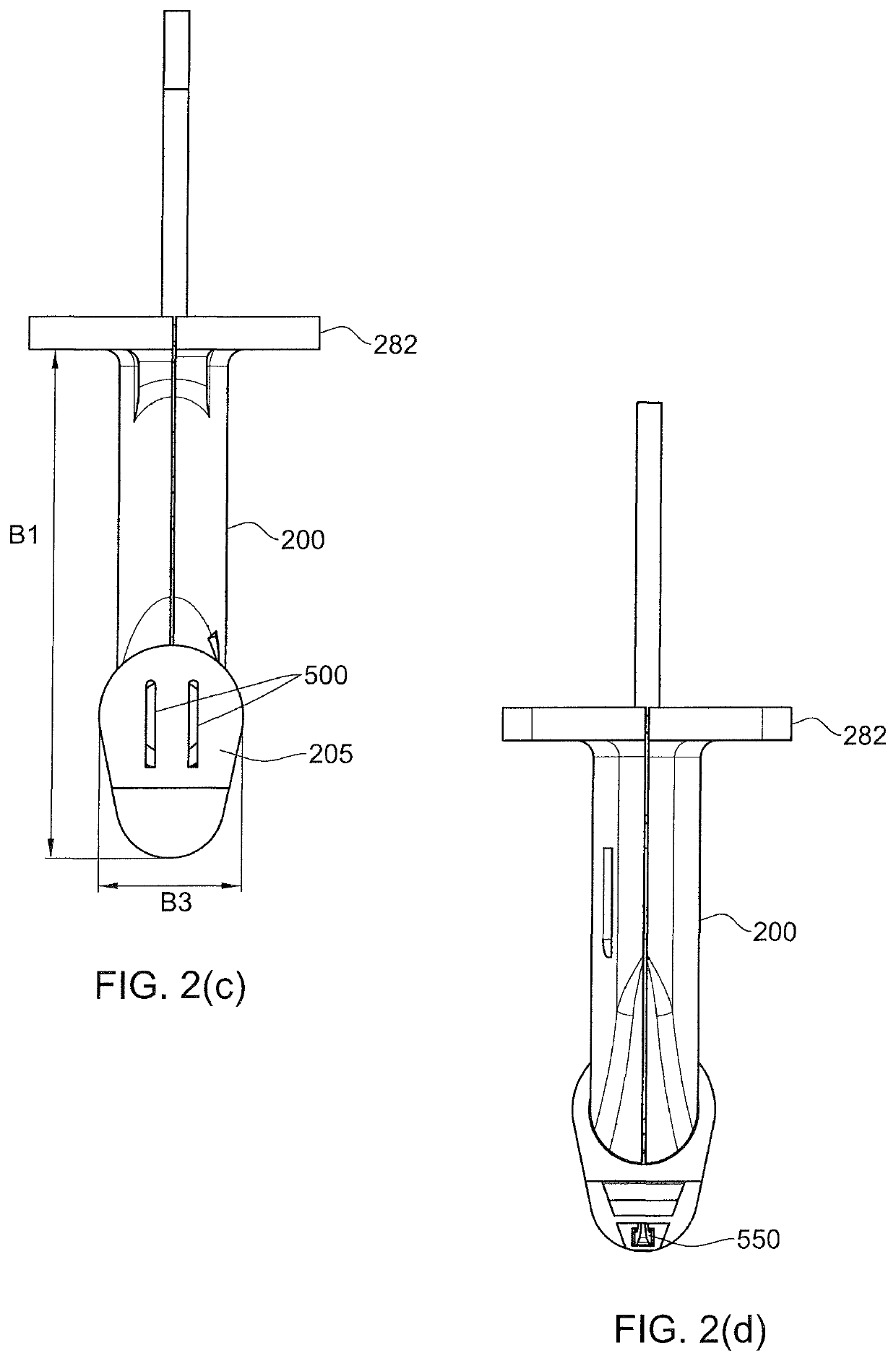
[0135]Referring to FIGS. 1, 2(a), 2(b), 2(c), 2(d), 3, a device for detecting presence of ice in an airstream AS according to a first example of the presently disclosed subject matter, generally designated 100, comprises a housing 200 defining a first chamber 230 and a second chamber 270.

[0136]In at least this example, the device 100 comprises, or at least is configured for being operatively connected to, at least to one air pressure sensor 300.

[0137]Furthermore, in at least this example, the device 100 comprises, or at least is configured for being operatively connected to, at least to an electromagnetic (EM) system 600.

[0138]A partition wall 250 separates the first chamber 230 from the second chamber 270.

[0139]The housing 200 in this example is made from two parts, a forward housing part 210 and an aft housing portion 220. In alternative variations of this example the housing 200 can be formed as an integral component, or alternatively can be formed as an assembly of more than two...


PUM


Abstract

A number of devices are provided for detecting presence of ice in an airstream. In some examples such device includes a housing defining a first chamber and a second chamber, and a partition wall separating the first chamber and the second chamber. The first chamber has at least one inlet opening on a front housing wall facing the airstream, and at least one outlet opening, smaller than the at least one inlet opening. The second chamber is configured for being operatively coupled to at least one electromagnetic (EM) system that is configured for transmitting EM energy to the first chamber at least via the partition wall, which is transparent and/or translucent with respect to the EM energy, the EM energy being configured for melting ice that can accrete with respect to the inlet opening. The device is configured for being operatively coupled to at least one air pressure sensor in fluid communication with the first chamber for detecting at least pressure changes in the first chamber responsive to ice accretion on the inlet opening.

Description

TECHNOLOGICAL FIELD[0001]The presently disclosed subject matter relates to icing detectors, particularly for aircraft.BACKGROUND ART[0002]References considered to be relevant as background to the presently disclosed subject matter are listed below:[0003]U.S. Pat. No. 5,823,474[0004]U.S. Pat. No. 9,013,332[0005]U.S. Pat. No. 6,010,095[0006]U.S. Pat. No. 5,296,853[0007]U.S. Pat. No. 5,551,288[0008]WO 2015 / 114624[0009]U.S. Pat. No. 4,553,137[0010]U.S. Pat. No. 6,206,325[0011]US 2011 / 067726[0012]DE 102011102804[0013]WO 2010 / 006946[0014]US 2007 / 176049[0015]US 2008 / 110254[0016]U.S. Pat. No. 5,400,144[0017]US 2014 / 263260[0018]US 2012 / 274938[0019]U.S. Pat. No. 5,760,711[0020]U.S. Pat. No. 4,461,178[0021]GB 1364845[0022]U.S. Pat. No. 5,191,791[0023]US 2013 / 175396[0024]U.S. Pat. No. 8,060,334[0025]US 2004 / 036630[0026]US 2002 / 158768[0027]US 2012 / 193477[0028]GB 563148[0029]US 2004 / 231410[0030]U.S. Pat. No. 6,091,335[0031]U.S. Pat. No. 5,484,121[0032]U.S. Pat. No. 4,797,660[0033]US 2010 / 110431[0...

Claims


Application Information

Patent Timeline
IPC IPC(8): B64D15/20
CPCB64D15/20G01L19/0007B65D15/00B64D15/22B64D2033/0233
Inventor MAROM, DANIEL
Owner ISRAEL AEROSPACE IND
Why Eureka
Try Eureka