Pump-turbine system

A turbine and equipment technology, applied in mechanical equipment, pumps, pump devices, etc., can solve problems such as difficulty in power adjustment of pump turbine equipment, and achieve good power adjustment effects

Inactive Publication Date: 2013-10-23
VOITH PATENT GMBH
View PDF7 Cites 2 Cited by
  • Summary
  • Abstract
  • Description
  • Claims
  • Application Information

AI Technical Summary

Problems solved by technology

However, this makes it difficult to adjust the power of this type of pump-turbine installation in the pump mode of operation

Method used


Image

  • Pump-turbine system
  • Pump-turbine system
  • Pump-turbine system

Examples


Embodiment Construction

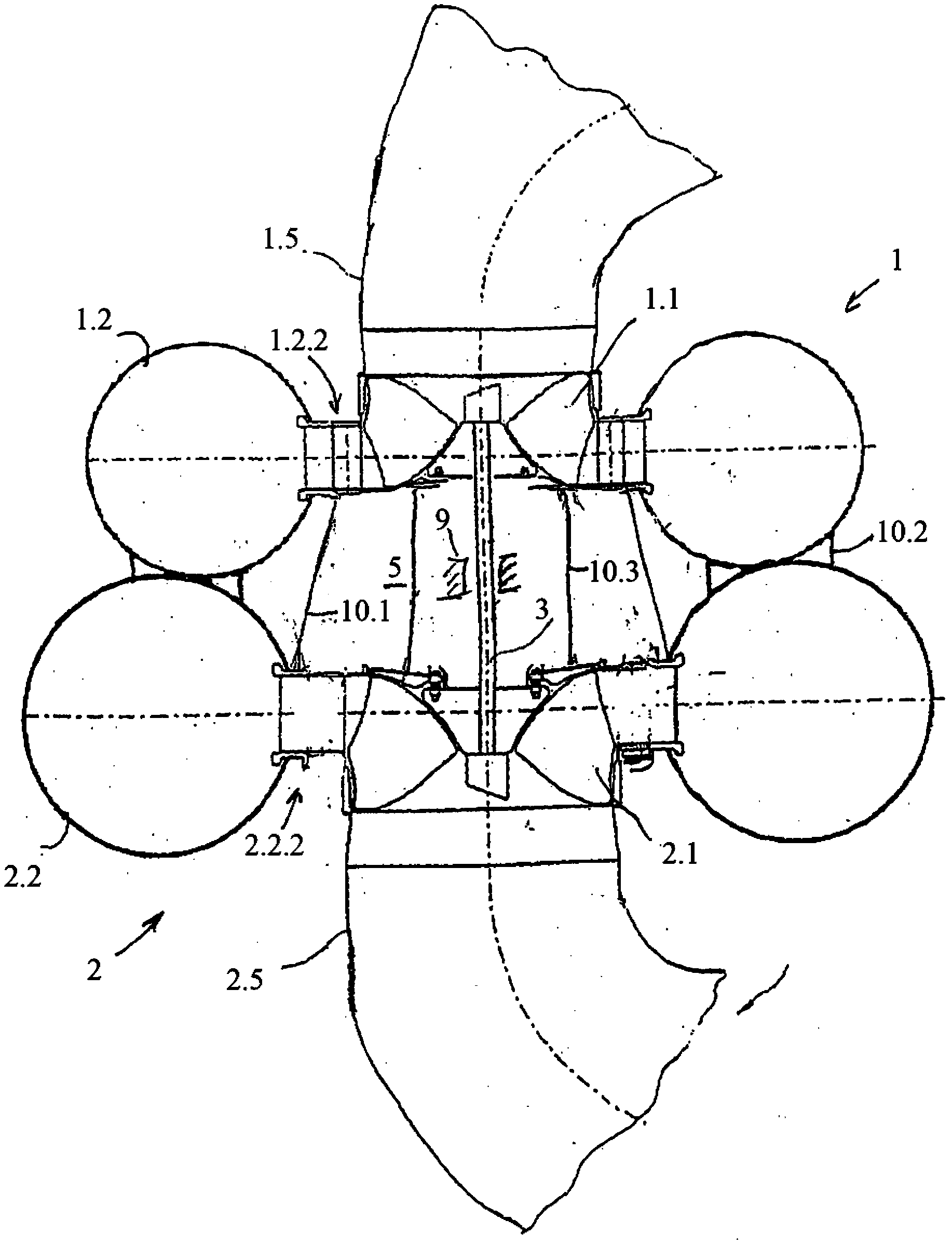
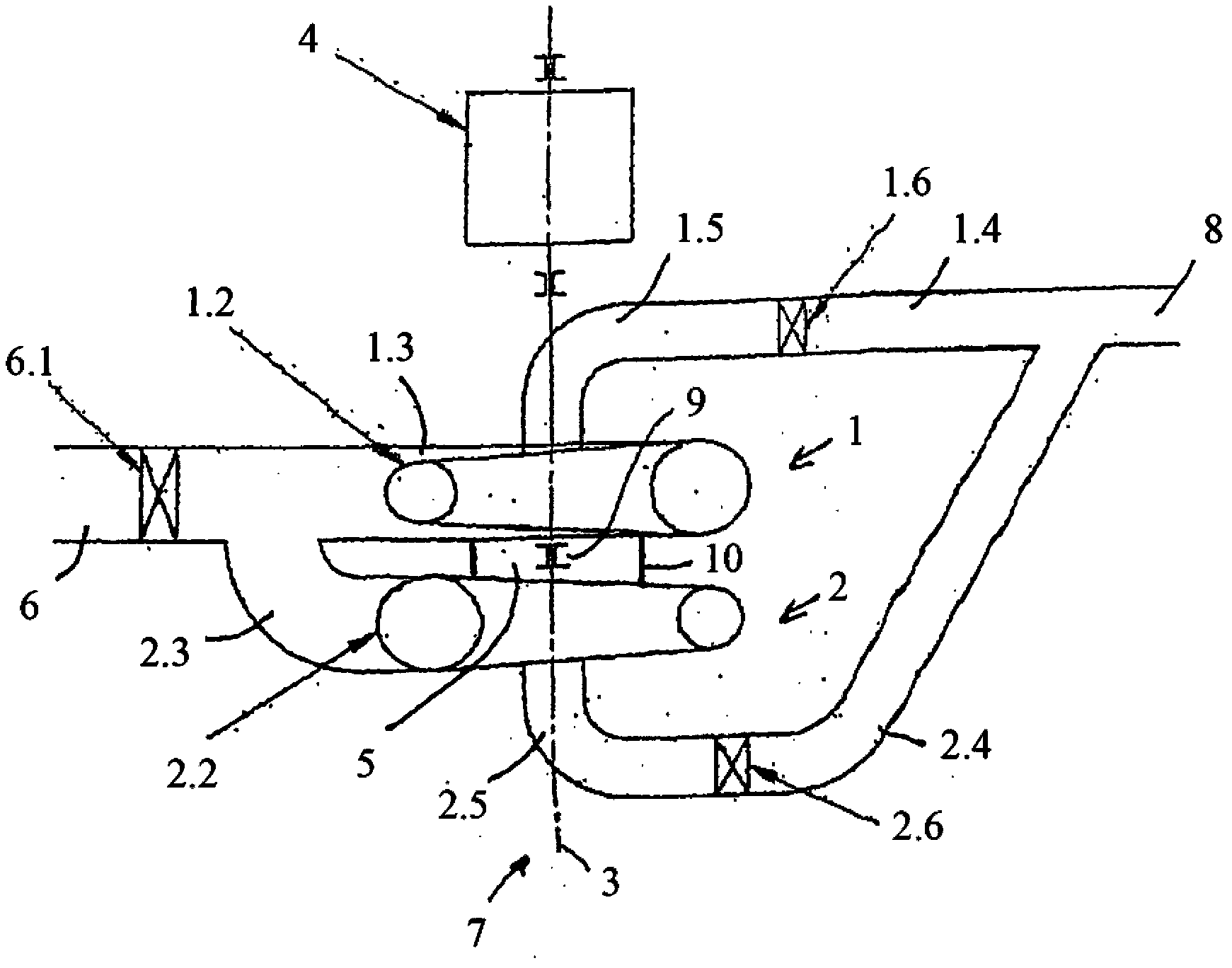
[0025] exist figure 1 The pump turbine arrangement shown in is constructed as follows: The turbine 1 comprises a turbine impeller 1.1 comprising a plurality of blades. The turbine wheel 1.1 is designed to be rotatably connected to the shaft 3 and its axis of rotation 7 is rotatably mounted. The turbine wheel 1.1 is surrounded by a turbine spiral housing 1.2. Furthermore, the edges of the guide vanes adjoin upstream of the turbine wheel 1.1.

[0026] The turbine 1 has a turbine suction line 1.5. It is connected after the vanes and comprises an inlet diffuser with an elbow connected thereto and a pipe connected thereto, the flow cross-section of which can widen in the flow direction of the water.

[0027] Currently, turbine 1 and pump 2 face each other directly. The latter means that the two hydraulic machines are arranged axially adjacent to each other without an electric machine generator between them. The pump 2 is located below the turbine 1 here.

[0028] The pump 2 c...


PUM


Abstract

The invention relates to a pump turbine system, comprising a turbine with a turbine impeller as well as a turbine spiral housing and a turbine suction pipe; a pump with a pump impeller as well as a pump spiral housing and a pump suction pipe; the two spiral housings are arranged to run in opposite directions; a shaft on which the turbine impeller and the pump impeller are non-rotatably arranged; an electrical machine that is in drive communication with the shaft or can be brought into such communication; the pressure lines of the two spiral housings open into a common pressure line; both suction pipes are each connected to suction lines, with both suction lines opening into a common suction line; with a separate shut-off element each being arranged in the suction lines.

Description

technical field [0001] The invention relates to a pump turbine device comprising a turbine with a turbine impeller, a turbine helical housing and a pump with a pump impeller and a pump helical housing. The pump and the turbine can be connected to the electric motor drive or can be brought into the drive connection. Background technique [0002] Here, Francis turbines or Barton turbines are considered to be used as turbines. Furthermore, both the pump and the turbine can be designed as single-stage or multi-stage, so that a combination of a single-stage turbine and a multi-stage pump or a combination of a multi-stage turbine and a single-stage or multi-stage pump is conceivable. [0003] The pump-turbine equipment of the pumped storage power station has two operating modes, that is, the operating mode of the turbine and the operating mode of the pump. In the latter case, the pump pumps water from the lower tank into the upper tank and is driven for this by an electric motor...

Claims


Application Information

Patent Timeline
Patent Type & Authority Applications(China)
IPC IPC(8): F03B3/10F03B3/18F03B11/02
CPCY02E10/226F04D13/06Y02E10/223F03B3/186F03B3/106F03B11/02Y02E10/20
Inventor 曼弗雷德·施图默尔
Owner VOITH PATENT GMBH
Why Eureka
Try Eureka