Method of Improving Airfoil Separation Stall by Radio Frequency Discharge Plasma Excitation

A radio frequency plasma and plasma technology, which is applied in the field of plasma flow control, can solve the problems of low heating efficiency and unstable discharge, and achieve the effects of high heating efficiency, stable discharge and prevention of electric shock.

Active Publication Date: 2020-05-22
AIR FORCE UNIV PLA
View PDF6 Cites 0 Cited by
  • Summary
  • Abstract
  • Description
  • Claims
  • Application Information

AI Technical Summary

Problems solved by technology

But the discharge is not stable enough and the heating efficiency is low

Method used


Image

  • Method of Improving Airfoil Separation Stall by Radio Frequency Discharge Plasma Excitation
  • Method of Improving Airfoil Separation Stall by Radio Frequency Discharge Plasma Excitation
  • Method of Improving Airfoil Separation Stall by Radio Frequency Discharge Plasma Excitation

Examples


Embodiment 1

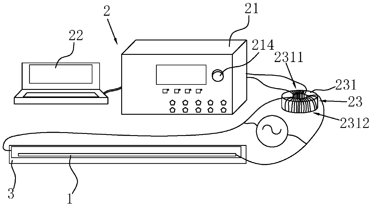
[0053] The invention discloses a device for radio frequency discharge plasma excitation to improve airfoil separation stall, such as figure 1 As shown, it includes a radio frequency exciter 1 for forming radio frequency plasma and a high voltage source 2 providing a high voltage environment for the radio frequency exciter 1 .

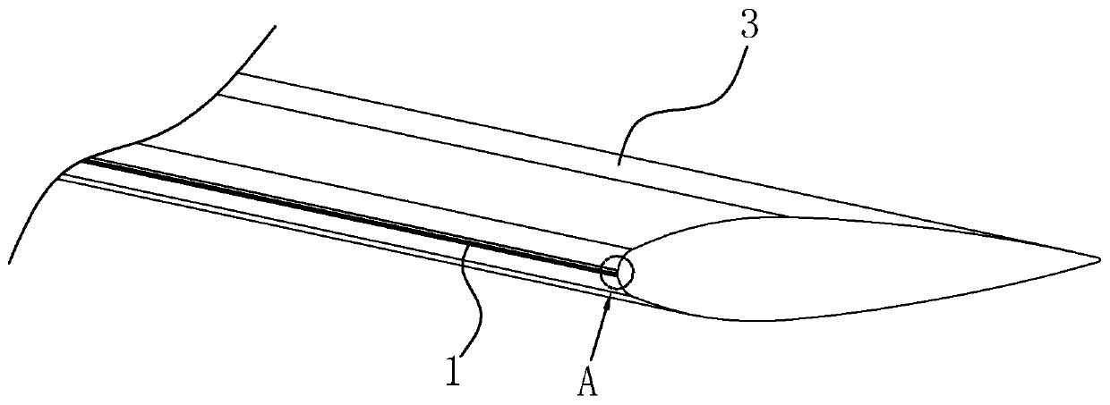
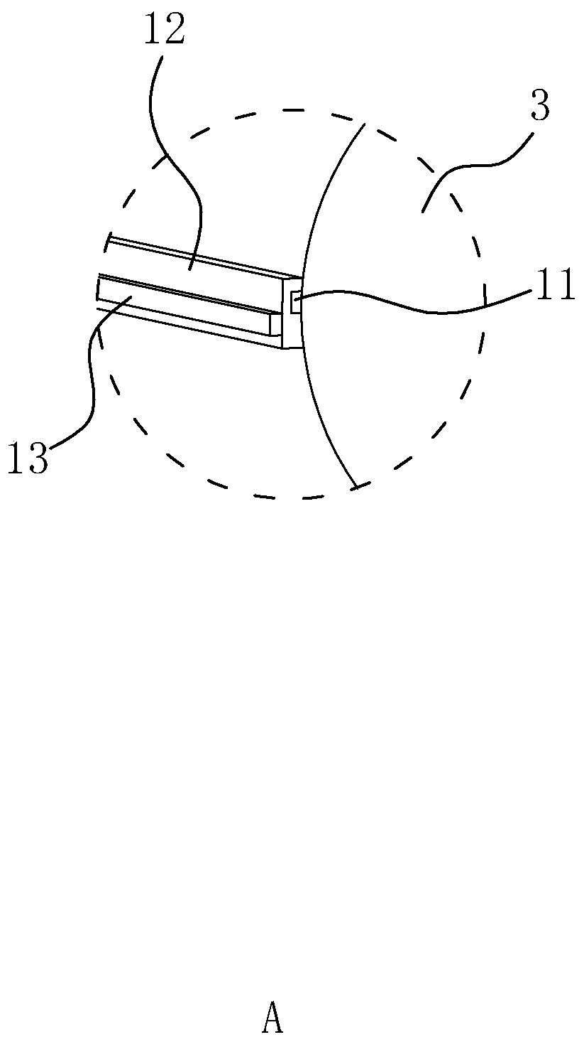
[0054] Such as figure 2 shown and image 3 As shown, the radio frequency exciter 1 is an important device for generating radio frequency plasma, and its discharge form is dielectric barrier discharge (DBD), including a covered electrode 11, an insulating dielectric layer 12 and an exposed electrode 13 that are stacked in sequence. Such as image 3 As shown, the cover electrode 11 is buried in the inner layer, and its side facing away from the insulating medium layer 12 is attached to the leading edge of the airfoil 3 (the NACA0015 airfoil is used as the test object in this embodiment of the present invention), along the span direction of the leading ...

Embodiment 2

[0061] The present invention also discloses a method for improving the airfoil separation stall by using the radio frequency discharge plasma excitation device disclosed above to improve the airfoil separation stall, which specifically includes the following steps:

[0062] S1: Connect the circuit, that is, connect the circuit of the high-voltage source 2, and connect the high-voltage source 2 and the RF exciter 1 at the same time. After connecting the circuit, provide sufficient loading voltage for the two electrodes of the RF exciter 1 to generate plasma by discharging, and the RF exciter The range of the voltage value between the two electrodes of the device 1 is 1KV-3KV, and the range of the current value passing through the RF exciter 1 is 3A-4A;

[0063] S2: arrange several pressure measuring points 31 along the span direction on the upper and lower surfaces of the airfoil 3;

[0064] S3: Install and fix the airfoil 3 in the wind tunnel system, set the angle of attack of t...


PUM


Abstract

The invention relates to a plasma flowing control technology and discloses a device and method for relieving separation stalling of an airfoil profile through radio-frequency discharge plasma excitation. The device comprises a radio-frequency exciter mounted at the front edge of the airfoil profile, and a high-voltage source for providing a high-voltage environment for the radio-frequency exciter;the radio-frequency exciter comprises a covered electrode, an insulating medium layer and a bare electrode which are sequentially attached in a stacked mode, wherein the face, deviating from the insulating medium layer, of the covered electrode is attached to the front edge of the airfoil profile, and the covered electrode is attached in the extending direction of the front edge of the airfoil profile; and the high-voltage source comprises a radio-frequency plasma power source, a signal modulation computer and a variable-voltage circuit, the output end of the radio-frequency plasma power source is connected to the primary terminal of the variable-voltage circuit, the signal modulation computer is connected with the radio-frequency plasma power source through a COM interface data line, andthe secondary terminal of the variable-voltage circuit is connected with the radio-frequency exciter. Reattachment of a separated adherent layer is promoted through radio-frequency plasma excitation,the aerodynamic performance of the airfoil profile is improved, and the stalling angle of attack and the lift coefficient are increased.

Description

technical field [0001] The invention relates to plasma flow control technology, in particular to a method for improving airfoil separation stall by radio frequency discharge plasma excitation. Background technique [0002] The wing is the main lifting surface of the aircraft, and the lift provided can account for more than 70% of the whole aircraft. The airfoil / wing is prone to flow separation when the aircraft is flying at a high angle of attack, resulting in a stall, which reduces lift and increases drag, seriously reduces the aerodynamic performance of the aircraft, and affects flight safety. [0003] Suppressing flow separation by means of flow control, delaying stall, and improving the aerodynamic performance of the aircraft at high angles of attack have become an important research direction in the field of aviation at home and abroad. As far as large aircraft such as transport aircraft are concerned, in order to increase the load capacity and range, relatively high l...

Claims


Application Information

Patent Timeline
Patent Type & Authority Patents(China)
IPC IPC(8): B64F5/60B64C3/36B64C23/00
CPCB64C3/36B64C23/00B64F5/60
Inventor 宋慧敏田苗梁华吴云贾敏魏彪赵光银金迪郭善广
Owner AIR FORCE UNIV PLA
Why Eureka
Try Eureka