
Suction hose fitting

A technology of hoses and fittings, applied in the direction of engine components, valve casing structure, cleaning method using liquid, etc.

Active Publication Date: 2016-02-03
ALFRED KARCHER GMBH & CO KG
View PDF6 Cites 2 Cited by
  • Summary
  • Abstract
  • Description
  • Claims
  • Application Information

AI Technical Summary

Problems solved by technology

As a result, when the high-pressure cleaner is switched off, ie at the end of the suction operation, water remains in the suction hose so that water cannot flow out of the suction hose fitting via the inlet opening of the housing

Method used


Image

  • Suction hose fitting
  • Suction hose fitting
  • Suction hose fitting

Examples


Embodiment Construction

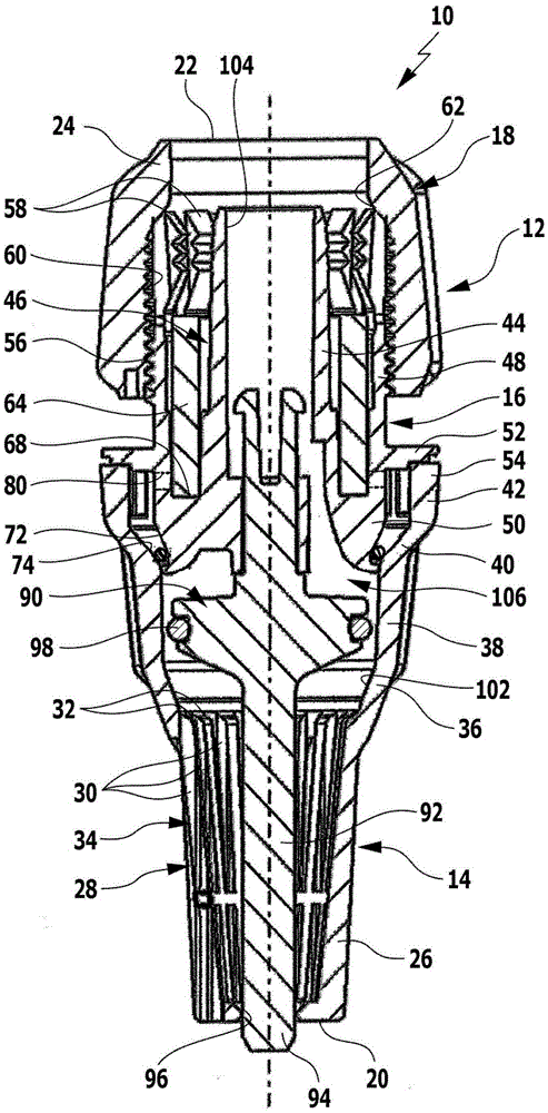
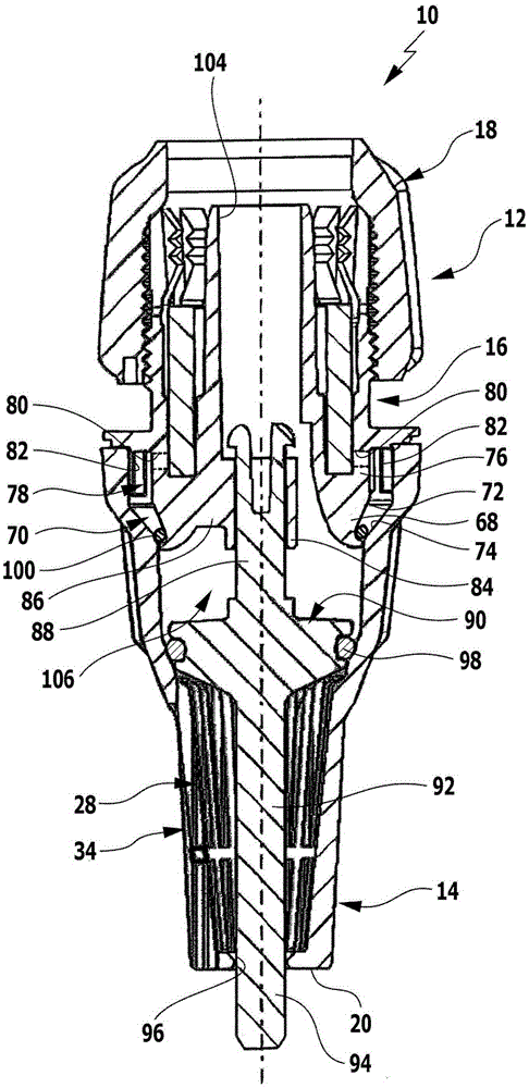
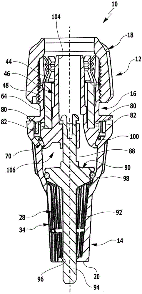
[0039] An advantageous embodiment of a suction hose fitting according to the invention, generally designated 10 , is shown schematically in the drawing. The suction hose fitting 10 has a housing 12 with a first housing part 14 , a second housing part 16 and a third housing part 18 . The first housing part 14 forms the front side 20 of the housing 12 and the second housing part 16 forms the rear side 22 of the housing 12 . The third housing part 18 can be screwed onto the second housing part 16 and protrudes with a rear end section 24 beyond the rear side 22 of the housing 12 .

[0040] The first housing part 14 forms a filter device in the form of a filter cage 28 with a plurality of housing openings 30 with a front housing section 26 adjoining the front side 20 , which housing openings are respectively located on two sides. Adjacent partitions 32 extend between them. The housing opening 30 forms overall an inlet opening 34 of the housing 12 .

[0041] Via a first conical w...


PUM


Abstract

The invention relates to a suction hose fitting (10) for connection to the suction hose of a high-pressure cleaning device, having a housing (12) which has an inlet opening (34) and an outlet opening (104), wherein a filter device (28) is arranged at the inlet opening (34) and a connection device (44, 48) for the suction hose is arranged at the outlet opening (104), and wherein a non-return valve, which closes in the direction of the inlet opening (34) and has a valve body (90) which can be moved to and fro between a closed position and an open position in the housing (12), is arranged in the housing (12). In order to develop the suction hose fitting in such a way that cleaning of the filter device (28) can be simplified, it is proposed according to the invention that the non-return valve can be manually released.

Description

technical field [0001] The invention relates to a suction hose fitting for connection to a suction hose of a high-pressure cleaner, with a housing having an inlet opening and an outlet opening, wherein a filter device is arranged at the inlet opening, and A coupling device for the suction hose is arranged at the outlet opening, and wherein a non-return valve closing in the direction of the inlet opening is arranged in the housing, the non-return valve having a valve body in the housing Can be moved back and forth between a closed position and an open position. Background technique [0002] This suction hose fitting is used in the suction hose of a high-pressure cleaner. With the aid of a high-pressure cleaner, the liquid, preferably water, is pressurized and then discharged via a pressure hose. For example, nozzles or cleaning lances can be arranged at the free end of the pressure hose, by means of which the liquid pressurized by the high-pressure cleaner can be aimed at t...

Claims


Application Information

Patent Timeline
IPC IPC(8): F16K15/06F16K27/02
CPCF16K15/06B08B2203/0247F16K27/0209
Inventor 托马斯·菲亚克安杰·克特曼斯文·迪恩贝格尔
Owner ALFRED KARCHER GMBH & CO KG
Learn More