Multi-stage switchable pilot-controlled valve arrangement

A technology of pilot control and valve device, which is applied in the direction of valve device, control valve and air release valve, valve operation/release device, etc. It can solve the problems of large volume and high cost of pipeline installation, and achieve the purpose of improving device safety and improving The effect of safety, high efficiency and full utilization

Active Publication Date: 2012-10-10
KNORR BREMSE SYST FUR SCHIENENFAHRZEUGE GMBH
View PDF4 Cites 1 Cited by
  • Summary
  • Abstract
  • Description
  • Claims
  • Application Information

AI Technical Summary

Problems solved by technology

Such a valve arrangement is relatively bulky and the installation effort of the individual components, especially its piping, appears to be relatively high

Method used


Image

  • Multi-stage switchable pilot-controlled valve arrangement
  • Multi-stage switchable pilot-controlled valve arrangement

Examples


Embodiment Construction

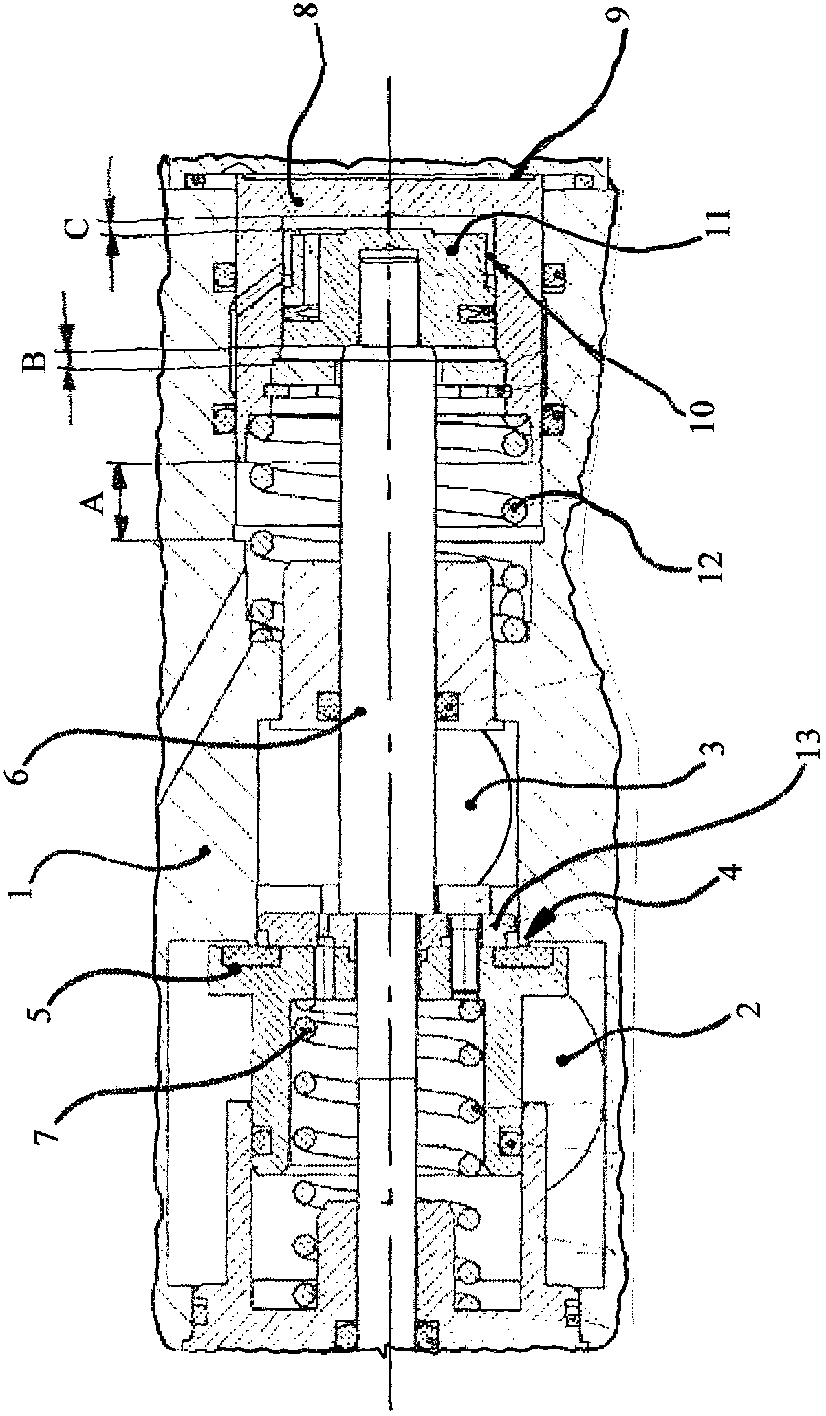
[0019] According to the illustration, the valve housing 1 (the region of the valve mechanism is only partially shown here) has a pressure supply connection 2 and a working line connection 3 . The valve mechanism has a normally closed 2 / 2 valve function, which is generated by the seat valve. The seat valve comprises a valve seat 4 fastened to the housing, which can be moved from the fully closed valve shown here by means of a coaxially extending and axially displaceable tappet 6 with its associated shut-off element 5 according to the pneumatic pilot control. The valve position passes over the throttled intermediate valve position into the open valve position. The valve return spring 7 , which is likewise integrated in the valve housing 1 , holds the shut-off element 5 of the seat valve in the closed control position during pressure-free pilot control.

[0020] The pneumatic pilot control consists of a first control piston 8 located in a first control chamber 9 formed in the va...


PUM


Abstract

The invention relates to a pilot-controlled valve arrangement having at least one valve mechanism mounted in a valve housing (1) for multi-stage switching of a compressed air flow between a feed pressure connection (2) and a working line connection (3), wherein a throttled compressed air flow can be switched in at least one switching stage by means of a throttle, wherein the pneumatic pilot control comprises a first control piston (8) mounted in a first control chamber (9) implemented in the valve housing (1) and comprising a coaxial recess for forming a second control chamber (10) in which a second control piston (11) is mounted, so that an additive control pressure application to the control chambers (9, 10) generates a telescope-like deployment of a ram (6) extending from the second control piston (11) for generating a multi-stage switching stroke for the valve mechanism, in order to implement the throttled compressed air flow in at least one switching stage of the valve mechanism present between the closed and the open valve setting.

Description

technical field [0001] The invention relates to a pilot-controlled valve device with at least one valve mechanism mounted in a valve housing for multistage control of the compressed air flow between a pressure supply connection and a working line connection, wherein the The throttle device controls the throttled compressed air flow in at least one control stage. Background technique [0002] The field of application of the invention is rail vehicle technology. In the field of pneumatic brake systems, a number of different multi-way valves are used to control the brake pressure and the associated auxiliary pressure. In order to charge or deflate compressed air units, in addition to simple distribution valves with 2 / 2 valve functions, more complex multi-way valves are required. The invention is particularly suitable for shut-off valves of pneumatic brake systems. [0003] According to the generally known prior art, in order to realize the closing module of the pneumatic bra...

Claims


Application Information

Patent Timeline
Patent Type & Authority Applications(China)
IPC IPC(8): F16K31/122B60T15/02
CPCB60T15/54B60T8/342B60T8/5018F16K31/1225
Inventor 海因茨・弗尔贝尔斯特芬・克拉塞尔特托马斯・加滕
Owner KNORR BREMSE SYST FUR SCHIENENFAHRZEUGE GMBH
Why Eureka
Try Eureka