Piston valve, especially for a pneumatic brake system in a vehicle

A technology of pneumatic braking and piston valve, applied in the direction of brakes, brake components, vehicle parts, etc., can solve the problems of high manufacturing cost and limited function of piston valve.

Active Publication Date: 2012-01-04
KNORR-BREMSE SYST FUER NUTZFAHRZEUGE GMBH
View PDF6 Cites 2 Cited by
  • Summary
  • Abstract
  • Description
  • Claims
  • Application Information

AI Technical Summary

Problems solved by technology

[0003] However, the disadvantage of such a piston valve is that its functionality is limited, since only a separate compressed air channel can only be opened or closed, and the operating functions must also be implemented externally, so that the budget for the equipment in which the piston valve is integrated is very high. high manufacturing cost

Method used


Image

  • Piston valve, especially for a pneumatic brake system in a vehicle
  • Piston valve, especially for a pneumatic brake system in a vehicle
  • Piston valve, especially for a pneumatic brake system in a vehicle

Examples


Embodiment Construction

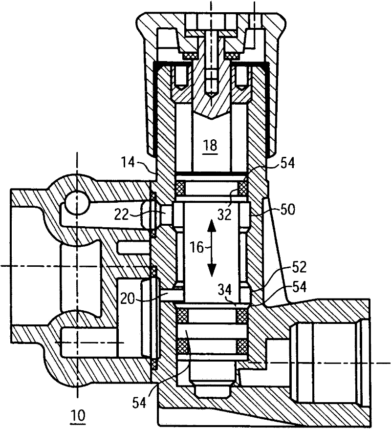
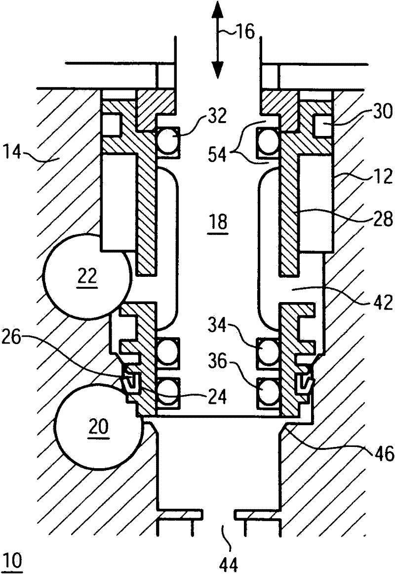
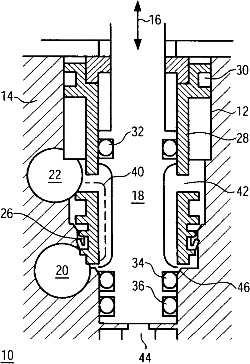
[0018] Figure 1 shows a piston valve according to the prior art. The piston valve 10 shown has a switching piston 18 that is movable in an axial direction 16 within a housing 14 . Arranged on the switching piston 18 are sealing rings 32 , 34 which are supported by a shoulder 54 . A further sealing ring 36 can be designed for secure sealing at all piston positions. The housing 14 includes a first port 20 and a second port 22 , which open into the region inside the housing 14 in which the movable switching piston 18 is arranged. During the movement of the switching piston 18 in the axial direction 16 , the sealing rings 34 , 36 are moved past the port 20 so that the compressed air passage between the first port 20 and the second port 22 is opened or closed. In that piston position in which the connection between ports 20 and 22 is closed, a further compressed air passage between first port 20 and third port 44 can be opened. In order to avoid damage to the sealing rings 32 , ...


PUM


Abstract

A piston valve (10), especially for a pneumatic brake system in a vehicle, is disclosed. Said piston valve (10) comprises a switching piston (18) which can be moved in an axial direction (16) within a zone (12) of a housing (14), at least two connections (20, 22) which are coupled to each other in a first switched position of the switching piston (18), and a sealing element (24) which seals a junction (38) between the at least two connections (20, 22) in at least one second switched position of the switching piston (18). According to the invention, the sealing element (24) is designed as a U-ring that has a flexible sealing lip (26) which acts as a check valve between the at least two connections (20, 22).

Description

technical field [0001] The invention relates to a piston valve, in particular for a pneumatic brake system for a vehicle, which piston valve has: a switching piston movable in the axial direction in the region of the housing; Mutual coupling in a first switching position of the switching piston; and a sealing element which seals the connection between at least two ports in at least one second switching position of the switching piston. Background technique [0002] Widely used piston valves are designed in such a way that, depending on their switching position, the ports arranged thereon are connected to one another or separated in different combinations. Their actuation can take place, for example, manually, electrically or pneumatically, wherein the switching piston is usually moved in the axial actuating direction within the piston valve. By moving the switching piston relative to the valve housing, the seal and / or the profile are moved relative to each other, so that di...

Claims


Application Information

Patent Timeline
Patent Type & Authority Applications(China)
IPC IPC(8): B60T15/02B60T17/04
CPCB60T15/027B60T17/04
Inventor 安德拉斯・福伊特亚诺什・托特阿蒂拉・米哈伊米歇尔・穆塞尔科内尔・坎托
Owner KNORR-BREMSE SYST FUER NUTZFAHRZEUGE GMBH
Why Eureka
Try Eureka