Sheet reversing apparatus and image forming apparatus

a technology of image forming apparatus and reversing sheet, which is applied in the directions of transportation and packaging, thin material processing, article delivery, etc., can solve the problems of difficult improvement of both-side printing process productivity, waste of time, and longer time required for a longer sheet, so as to reduce the time required for reversing and improve the productivity of both-side image forming process, the effect of avoiding deterioration of print quality

Inactive Publication Date: 2006-08-17
CANON KK
View PDF7 Cites 12 Cited by
  • Summary
  • Abstract
  • Description
  • Claims
  • Application Information

AI Technical Summary

Benefits of technology

[0021] In the sheet reversing apparatus and the image forming apparatus of the present invention, since a surface of a conveying belt is twisted by a predetermined angle between a conveying start position and a conveying end position and a sheet is conveyed by being attracted to such conveying belt, it is possible to reduce a time required for sheet reversing, thereby improving the productivity at the both-side image forming process. Also as the sheet is not locally nipped but entirely attracted in the conveying, in comparison with a prior apparatus in which the sheet is reversed along a conveying path formed in a shape of a Mebius' belt, it is rendered possible to avoid a print quality deterioration such as a trace of nipping on the sheet. Also the stability in sheet conveying can be improved as a flapping of the sheet at the conveying can be prevented.

Problems solved by technology

In such sheet reversing apparatus of switchback type, it is necessary to stop and reverse the rollers for sheet switchback, thus resulting in a waste in time.
Also a guide member for temporarily holding the sheet at the sheet switchback is occupied until the entire sheet passes through such guide, so that a longer time is required for a longer sheet and the productivity at the both-side printing process is difficult to improve.
However, in such sheet reversing apparatus in which the sheet is guided along a conveying path having a shape of a Mebius' belt, since the sheet is nipped by the nipping craws, a trace of the nipping claws is formed on the sheet surface and the sheet tends to cause, in the course of conveying, a flapping in a portion other than the part nipped by the nipping claws thereby causing a damage on the sheet.
Also the sheet tends to cause, in the course of conveying, a flapping in a portion other than the part nipped by the belt thereby causing a damage on the sheet.

Method used


Image

  • Sheet reversing apparatus and image forming apparatus
  • Sheet reversing apparatus and image forming apparatus
  • Sheet reversing apparatus and image forming apparatus

Examples


Embodiment Construction

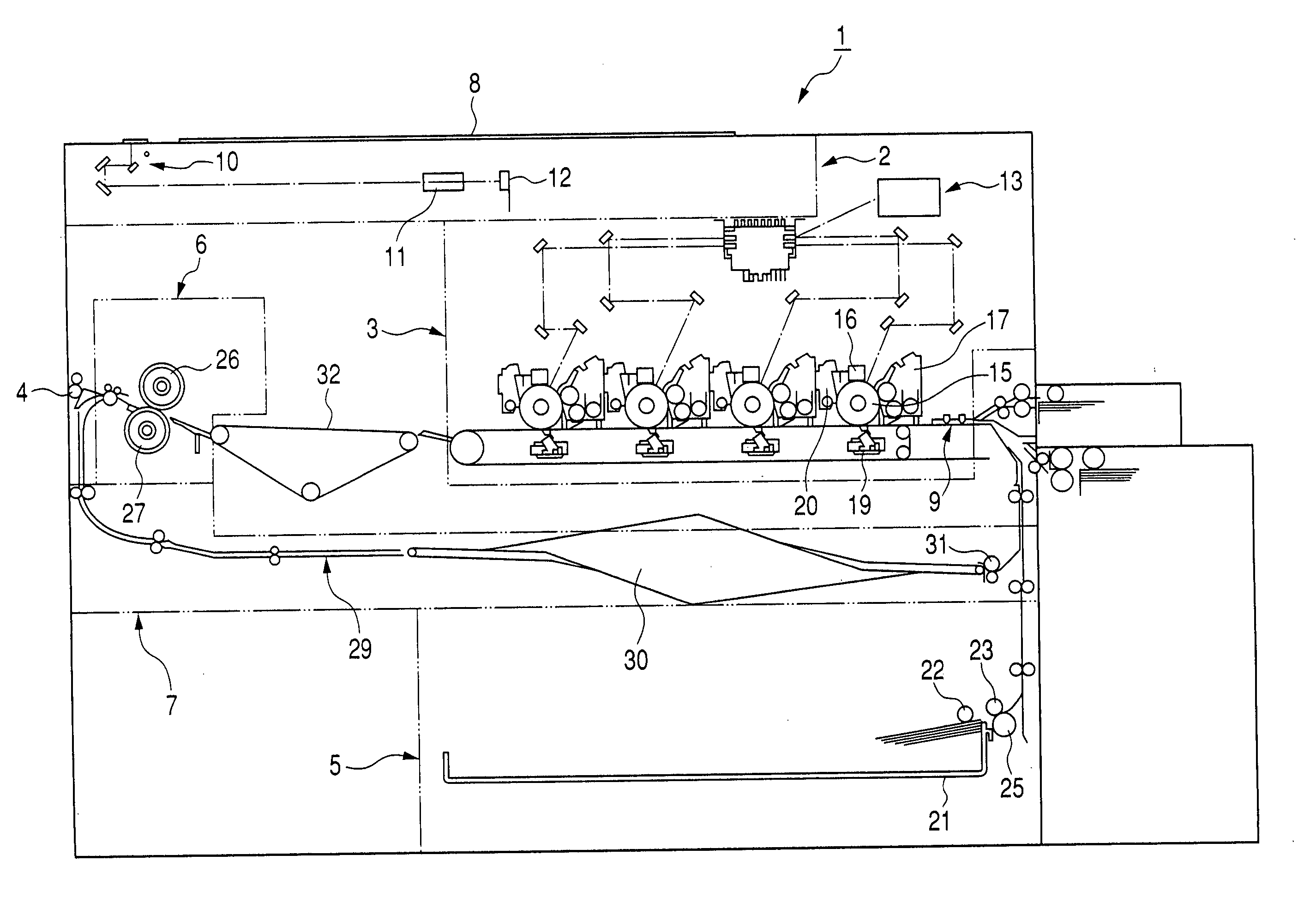
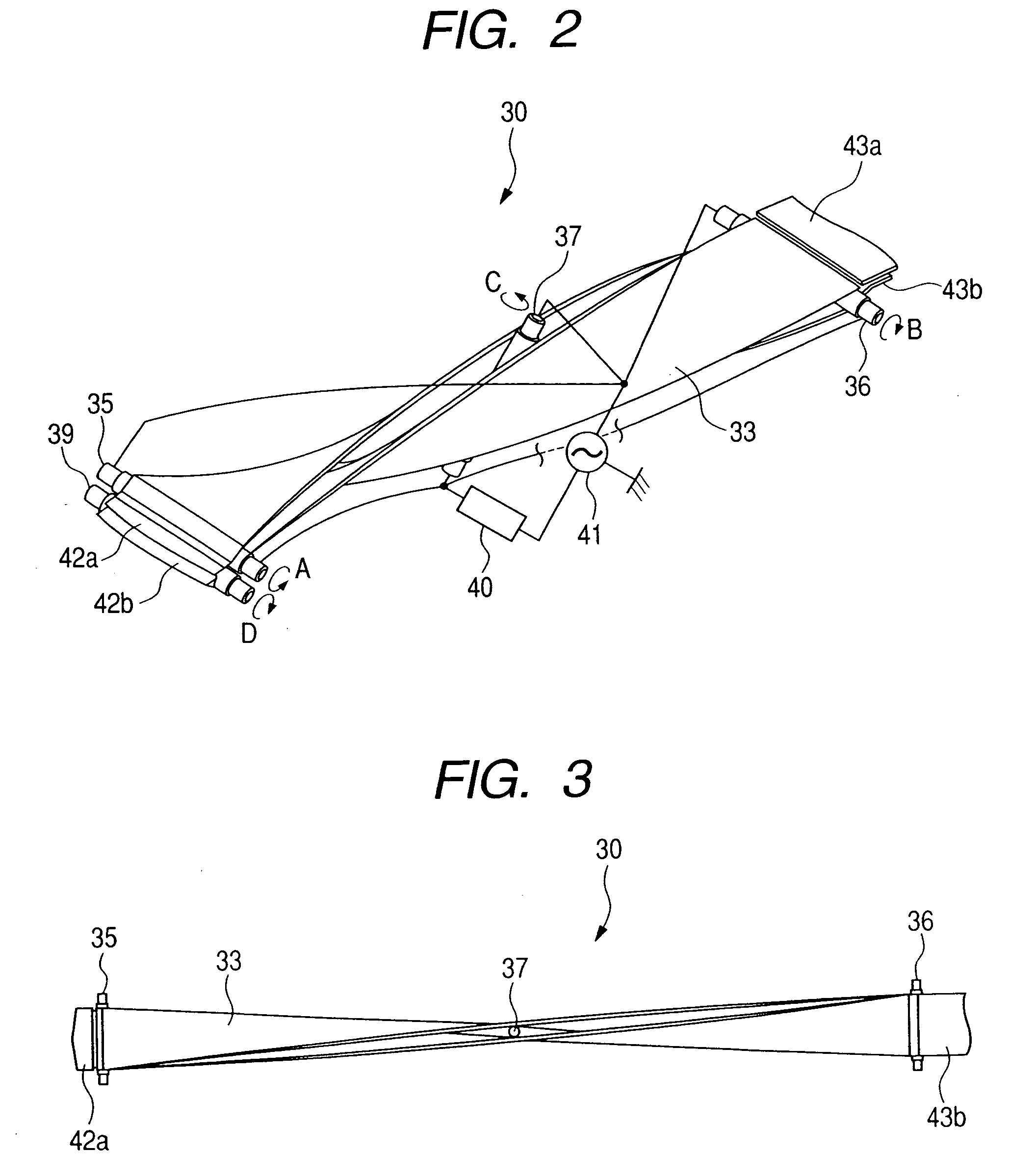
[0033] In the following, a sheet reversing apparatus and an image forming apparatus embodying the present invention will be explained with reference to FIGS. 1 to 8.

[0034]FIG. 1 is a lateral cross-sectional view of an image forming apparatus embodying the present invention; FIG. 2 is a perspective view of a sheet reversing apparatus of the present invention as a reversing unit; FIG. 3 is a plan view of a reversing unit embodying the present invention; FIG. 4 is a lateral view of a reversing unit embodying the present invention; FIG. 5 is a lateral view showing a conveying start position in the reversing unit embodying the present invention; FIG. 6 is a lateral view showing a conveying end position in the reversing unit embodying the present invention; FIG. 7 is a lateral view showing another sheet separating method from an attraction belt 33 of the embodiment; and FIG. 8 is a perspective of the reversing unit of the embodiment in the course of sheet conveying.

[0035] The image form...


PUM

PropertyMeasurementUnit
angleaaaaaaaaaa
angleaaaaaaaaaa
angleaaaaaaaaaa

Abstract

In a sheet reversing unit, an attraction belt is supported, in a 180° twisted position, between a belt driving roller at a conveying start position and a belt driving roller at a conveying end position, and a sheet is conveyed by providing the attraction belt with an electrostatic force from an AC power supply and thus by being attracted to the attraction belt, whereby the sheet is reversed.

Description

BACKGROUND OF THE INVENTION [0001] 1. Field of the Invention [0002] The present-invention relates to an image forming apparatus such as a copying apparatus, a printer or a facsimile apparatus, and more particularly to an apparatus for reversing a sheet in case of forming images on both sides of a sheet. [0003] 2. Related Background Art [0004] There is known an image forming apparatus such as a copying -apparatus, a printer or a facsimile apparatus, that is provided with a mode of forming images on both front and rear sides of a sheet (hereinafter called both-side image forming mode). In such both-side image forming mode, image formations on both sides of a sheet are achieved by reversing a sheet by a sheet reversing apparatus provided in the image forming apparatus. [0005]FIG. 10 is a lateral cross-sectional view showing a configuration of a sheet reversing apparatus of a prior switchback type provided for the both-side image forming mode. [0006] A sheet reversing apparatus 100b is ...

Claims


Application Information

Patent Timeline
Patent Type & Authority Applications(United States)
IPC IPC(8): B65H29/00
CPCB65H5/004B65H15/00B65H29/16B65H2301/33212B65H2301/33224B65H2301/5132B65H2301/5133B65H2301/5322B65H2404/261B65H2555/41B65H15/012
Inventor AGATA, JUN
Owner CANON KK
Why Eureka
Try Eureka