Energy transfer apparatus

a technology of energy transfer apparatus and motor, which is applied in the direction of electrical apparatus, dynamo-electric machines, belts/chains/gearings, etc., can solve the problems of limited efficiency ratio of generators and motors, and reduce the effect of the efficiency ratio

Active Publication Date: 2006-08-17
CONCEPT FISET
View PDF20 Cites 16 Cited by
  • Summary
  • Abstract
  • Description
  • Claims
  • Application Information

AI Technical Summary

Problems solved by technology

Generators and motors have a limited efficiency ratio which typically decreases with the increase in temperature resulting from a high frequency of revolutions of the rotor during operation.

Method used


Image

  • Energy transfer apparatus
  • Energy transfer apparatus
  • Energy transfer apparatus

Examples


example

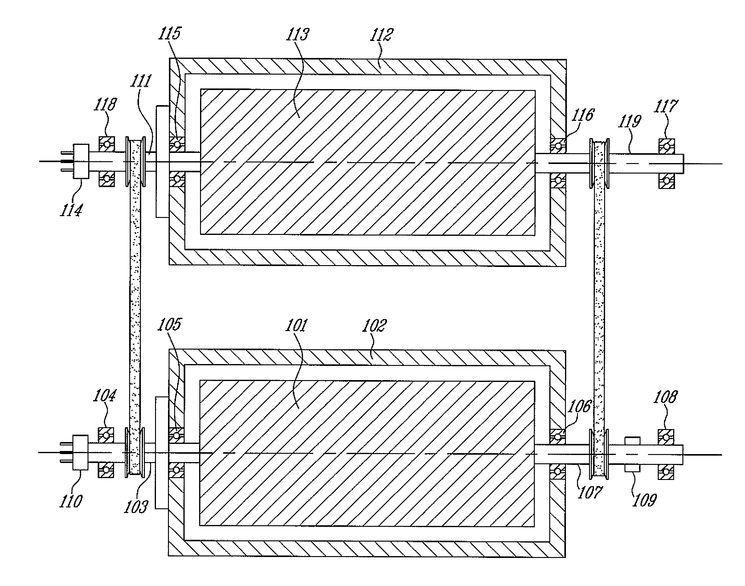
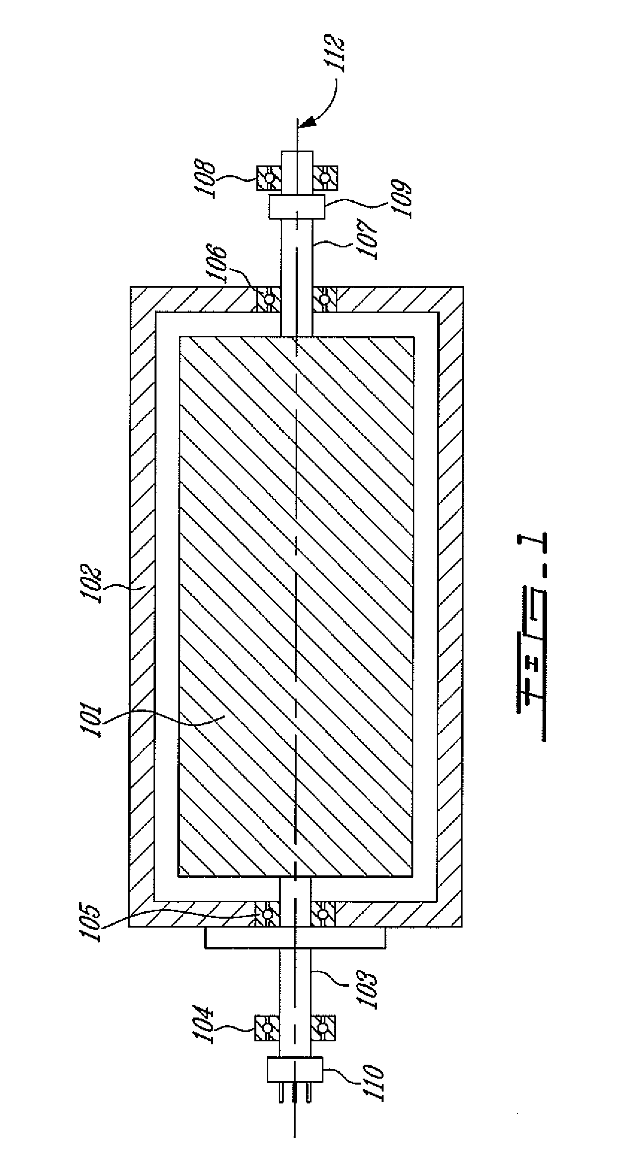
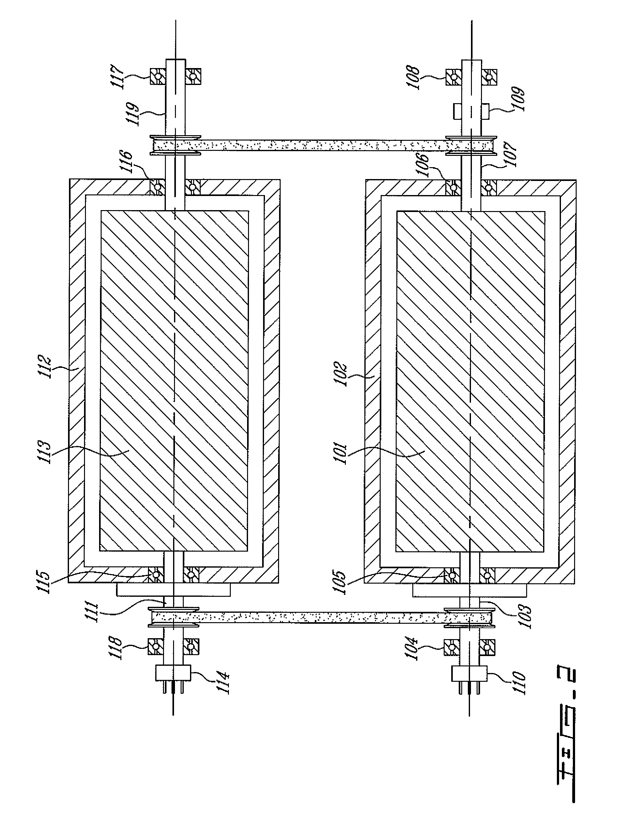
[0032] A bi-rotary 1 force motor was coupled to a bi-rotary generator with both rotors and both stators directly coupled by two independent straps in a ratio of 1:1. At first, the generator output was not subjected to electrical resistance, and when the motor was powered, the rotors accelerated to high RPM. The stators were pivoting very slowly in the opposite rotational direction. In fact, since the stators are heavier than the rotors, and their mass is spaced further from the rotation axis, they have a much higher moment of inertia and do substantially do not pivot.

[0033] Then, resistance in the form of light bulbs was added to the generator coils. The angular speed of the stators began increasing, whereas the angular speed of the rotors began decreasing accordingly. Although the speed differential between rotors and stators was kept approximately constant, the kinetic energy of the system increased due to the flywheel effect of the high moment of inertia pivoting of the stators....


PUM


Abstract

A motor and a generator both comprising a rotor and a stator, wherein said rotor and said stator of both said motor and said generator can rotate about a common axis, and wherein both said stators are coupled, and both said rotors are coupled, for one to induce rotation to the other, and wherein the rotation energy may be transferred to a system.

Description

CROSS-REFERENCE TO RELATED APPLICATION [0001] This application is a continuation of PCT patent application serial number PCT / CA2004 / 001853 filed Oct. 21, 2004, designating the United States, the specification of which is hereby incorporated by reference and claims priority of U.S. provisional patent application 60 / 512,696 filed on Oct. 21, 2003, the specification of which is hereby incorporated by reference.FIELD OF THE INVENTION [0002] The present invention relates to generators and motors, and more specifically, to configurations of generators and motors with two rotating parts. BACKGROUND OF THE INVENTION [0003] Machines used to transform other forms of energy (such as heat) into mechanical energy are known as engines. The electric motor transforms electrical energy into mechanical energy. Its operation is the reverse of that of the electric generator, which transforms the mechanical energy (for example of falling water or steam) into electrical energy. [0004] The generator opera...

Claims


Application Information

Patent Timeline
Patent Type & Authority Applications(United States)
IPC IPC(8): F02B63/04H02K47/20H02K23/60F16H7/02F16H9/04H02K16/00H02K53/00
CPCF16H7/023F16H9/04H02K16/00H02K53/00H02K57/00H02K99/00
Inventor FISET, JEAN
Owner CONCEPT FISET
Why Eureka
Try Eureka