Magnetic resonance imaging system

Inactive Publication Date: 2006-08-17
HITACHI MEDICAL CORP
View PDF51 Cites 16 Cited by
  • Summary
  • Abstract
  • Description
  • Claims
  • Application Information

AI Technical Summary

Benefits of technology

[0025] In the two- or three-dimensional dynamic measurement using the contrast medium, too, the image reliably catching the desired time phase can b

Problems solved by technology

In the case of three-dimensional imaging, in particular, the operation of extracting only three-dimensional data constituting an artery phase (time phase in which the artery is mainly depicted) necessary for the diagnosis

Method used


Image

  • Magnetic resonance imaging system
  • Magnetic resonance imaging system
  • Magnetic resonance imaging system

Examples


Example

FIRST EMBODIMENT

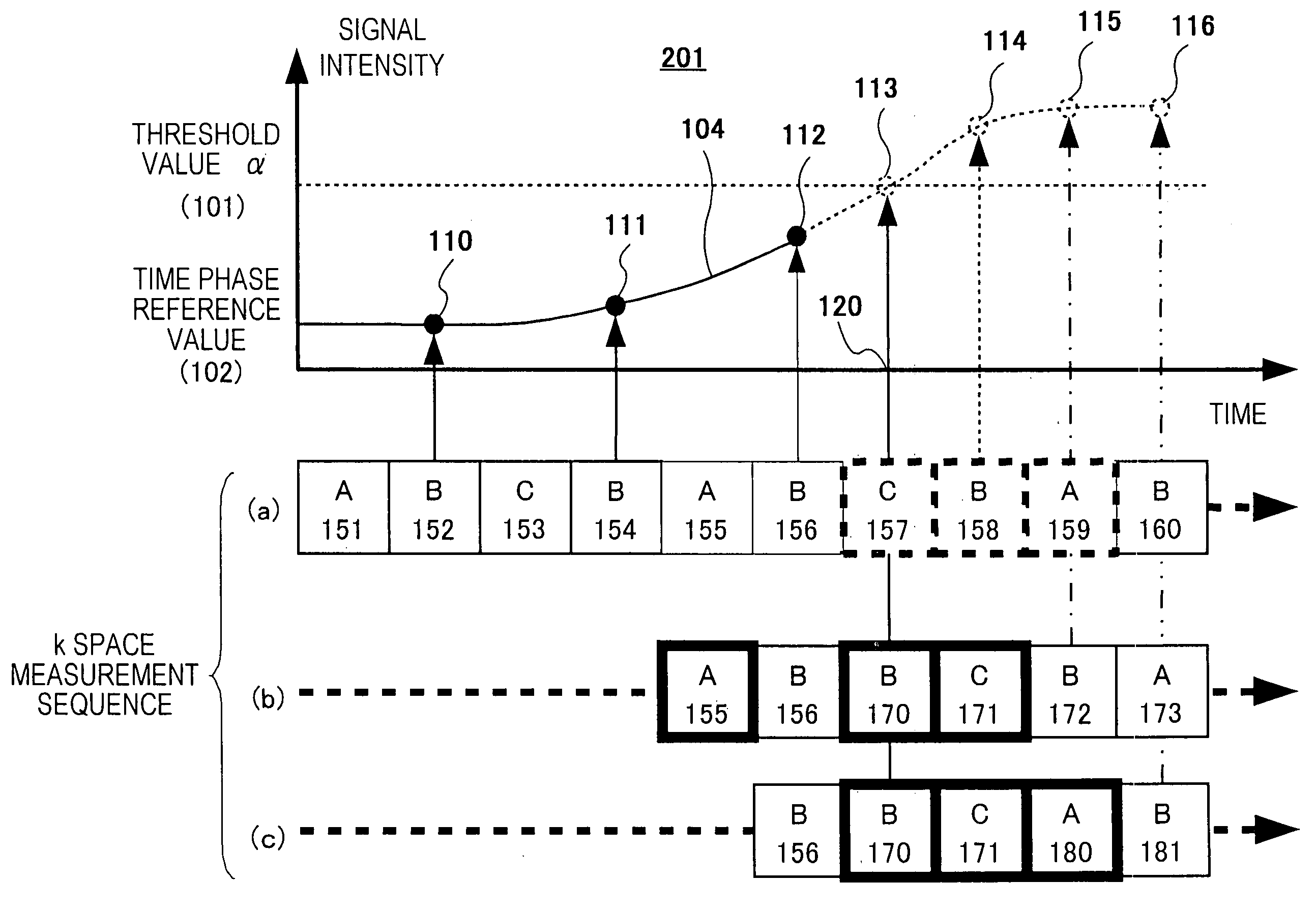
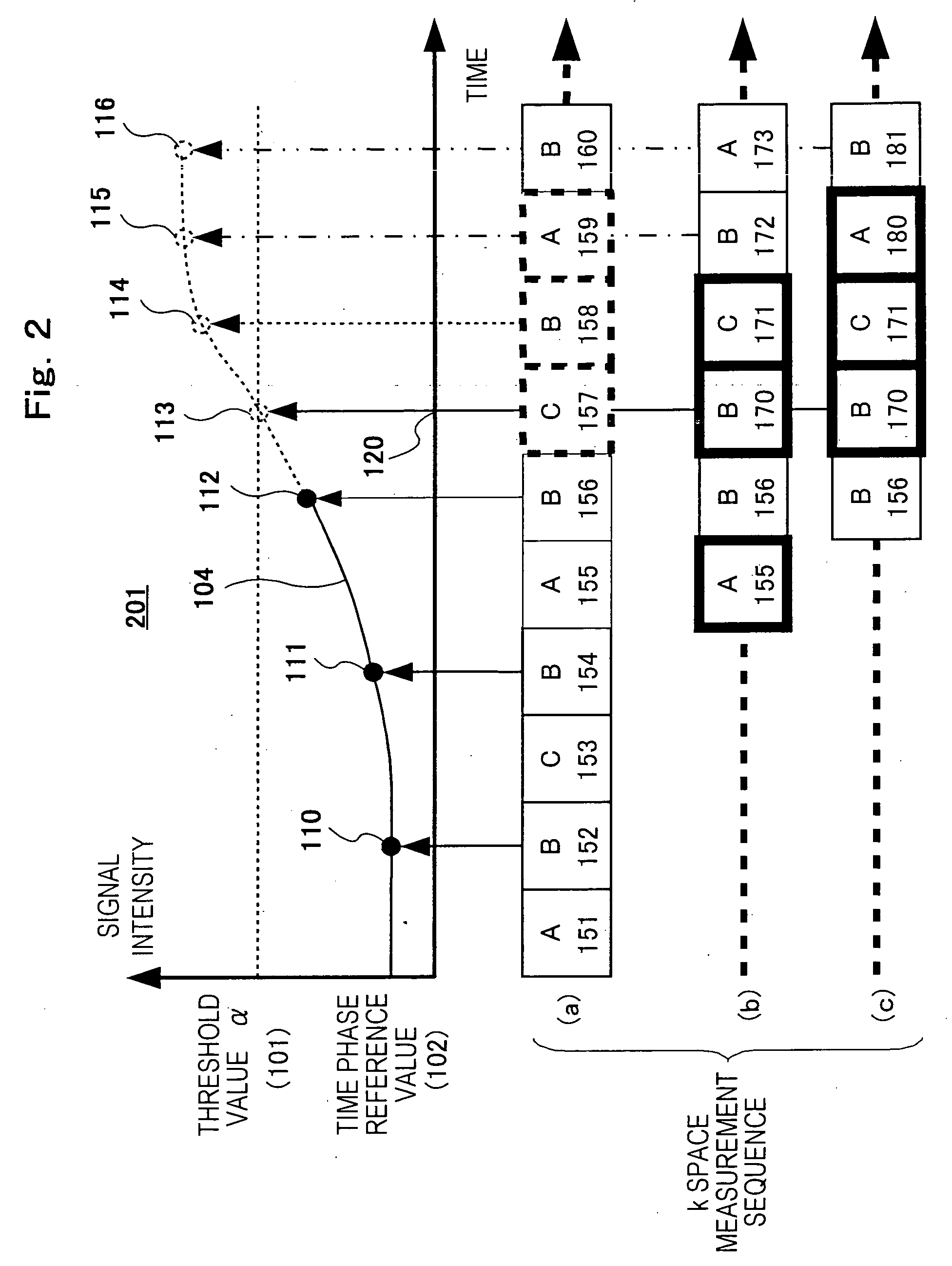
[0063] Next, the MRI apparatus according to the first embodiment of the invention will be explained. When the k space data of a plurality of time phases is measured by conducting dynamic measurement, the measurement sequence of each measurement area to be measured in time series is controlled (that is, arbitrarily changed) so that the measurement period of the high-repetitive frequency measurement area contains the artery phase (the time phase in which the artery is mainly depicted).

[0064]FIG. 2 shows an example of the first embodiment. FIG. 2 shows the mode of the time change of the time phase evaluation value by the three-dimensional dynamic measurement by using the MRI apparatus described already and an example of the measurement sequence of each measurement area divided.

[0065] Here, the term “time phase evaluation value” means an addition value after the k space origin data of the high frequency measurement area or uni-dimensional echo data in the readout dire...

Example

SECOND EMBODIMENT

[0111] Next, the MRI apparatus according to the second embodiment of the invention will be explained. This embodiment selects the high frequency measurement area closest to a desired artery phase and the low repetitive-frequency measurement areas close time-wise to the high frequency measurement area and constituting other areas of the k space after the dynamic measurement is executed to measure the k space data of a plurality of time phases. In other words, this is the form that does not predict the start timing of the artery phase while acquiring the time phase evaluation values in the first embodiment described above but serially measures each measurement area in a predetermined measurement sequence, detects a desired artery phase after the end of the dynamic measurement and acquires the image.

[0112]FIG. 5 shows an example of this embodiment. FIG. 5 shows an example of the mode of the time change of the time phase evaluation values measured and the measurement ...


PUM


Abstract

A magnetic resonance imaging system in which measurement data (k space data) of arterial phase is extracted easily (and instantaneously) after imaging a plurality of time phases including the arterial phase and its image can be displayed in dynamic MRA measurement employing a contrast medium. Dynamic measurement is thereby carried out using a means for extracting the time phase evaluation values (e.g. the origin data in k space) in respective time phases and then automatically extracting a data set including a time phase where the time phase evaluation value reaches a specified threshold value.

Description

TECHNICAL FIELD [0001] This invention relates to a magnetic resonance imaging (hereinafter called “MRI”) apparatus for acquiring a tomogram of a desired portion of a subject by utilizing a nuclear magnetic resonance (hereinafter called “NMR”) phenomenon. More particularly, the invention relates to an MRI apparatus capable of easily depicting an artery phase image of bloodstream motion containing a contrast agent when the blood vessel system is depicted by using a T1 shortening type contrast agent such as Gd-DTPA. BACKGROUND ART [0002] A magnetic resonance imaging apparatus measures a density distribution of an atomic nucleus spin (hereinafter merely called “spin”), a relaxation time distribution, etc, at a desired inspection portion in a subject by utilizing the NMR phenomenon and displays an image of an arbitrary section of the subject from the measurement data. Particularly, the magnetic resonance imaging apparatus has an imaging function called “contrast enhanced MR angiography” ...

Claims


Application Information

Patent Timeline
IPC IPC(8): A61B5/05G01R33/563G01R33/567
CPCG01R33/563G01R33/5676A61B5/055
Inventor ABE, TAKAYUKITAKAHASHI, TETSUHIKO
Owner HITACHI MEDICAL CORP
Why Eureka
Try Eureka