Heat pipe cooling system and thermal connector thereof

a cooling system and heat pipe technology, applied in the field of cooling systems, can solve the problems of increasing the spatial occupation of the cooling fin, increasing the energy consumption, and the conventional heat dissipation method will become a bottleneck, and achieve the effect of low energy consumption

Inactive Publication Date: 2006-08-24
ADVANCED THERMAL DEVICES
View PDF20 Cites 28 Cited by
  • Summary
  • Abstract
  • Description
  • Claims
  • Application Information

AI Technical Summary

Benefits of technology

[0023] In the present invention, the heat from a heat source is transferred to an object attached to the thermal conductive block through the connecting pipeline of a heat pipe cooling system. Then, the heat is dissipate...

Problems solved by technology

However, as the quantity of heat generated by the device is increased, the conventional heat dissipation method will become a bottleneck.
Yet, if the heat-generating device is disposed inside the limited space of an enclosed housing, then increasing the surface area of fins will increase the spatial occupation of ...

Method used


Image

  • Heat pipe cooling system and thermal connector thereof
  • Heat pipe cooling system and thermal connector thereof
  • Heat pipe cooling system and thermal connector thereof

Examples


Embodiment Construction

[0039] Reference will now be made in detail to the present preferred embodiments of the invention, examples of which are illustrated in the accompanying drawings. Wherever possible, the same reference numbers are used in the drawings and the description to refer to the same or like parts.

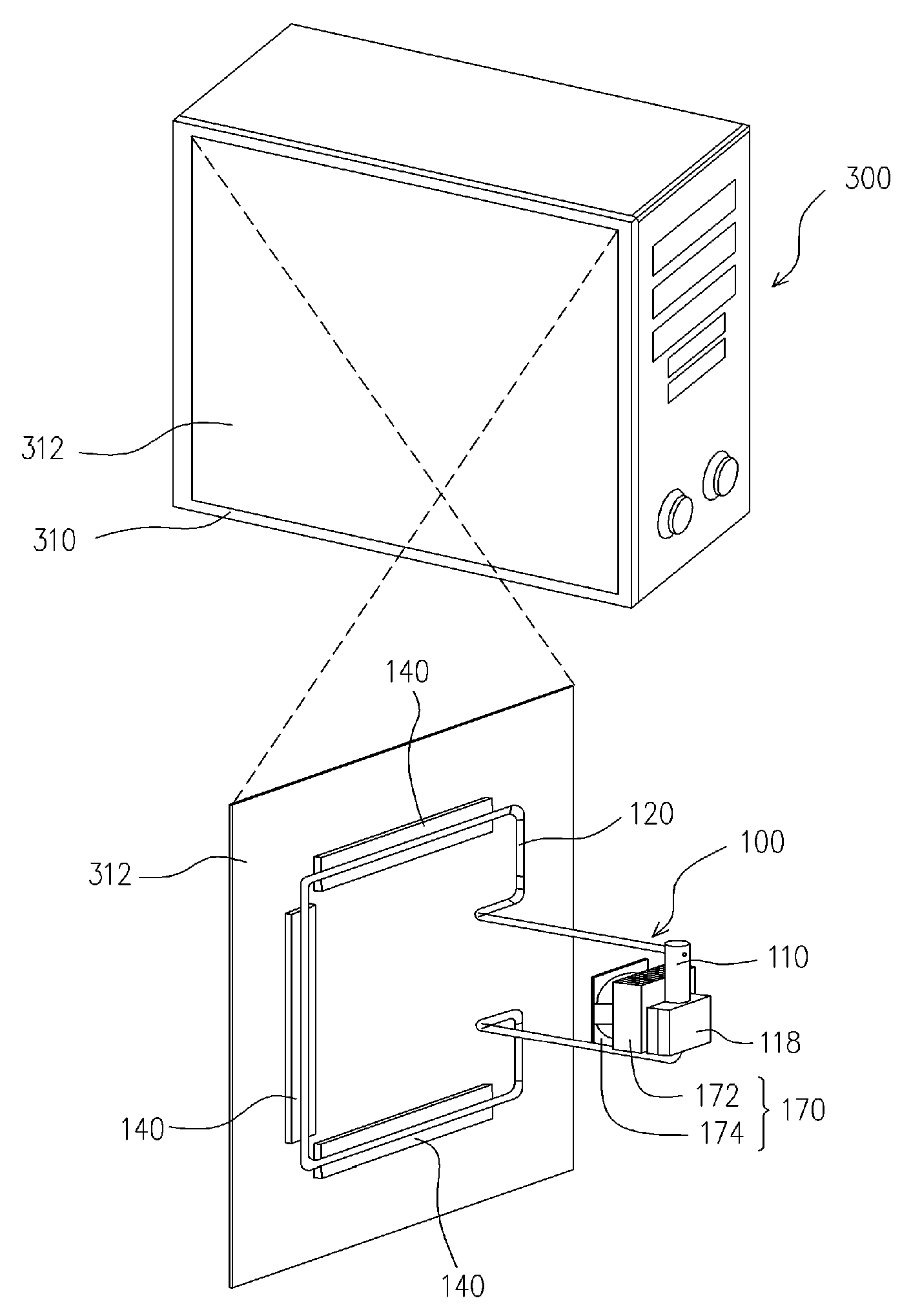
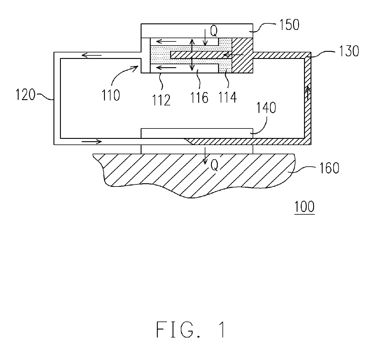
[0040]FIG. 1 is a schematic cross-sectional view of a heat pipe cooling system according to one embodiment of the present invention. As shown in FIG. 1, the heat pipe cooling system 100 mainly comprises an evaporator 110, a connecting pipeline 120, a working fluid 130 and a thermal connector 140. A heat-generating device 150 is attached to the evaporator 110 and the connecting pipeline 120 is linked to the evaporator 110. The working fluid 130 is injected into the closed loop formed by the evaporator 110 and the connecting pipeline 120. The evaporator 110 further comprises an evaporation wall 112, a wick structure 114 and a vaporizing groove 116. The wick structure 114 is disposed inside the evapor...


PUM


Abstract

A heat pipe cooling system comprising an evaporator, a pipeline, a working fluid and a thermal connector is provided. The evaporator is connected to a heat-generating element, and the pipeline is connected to the evaporator. The working fluid is injected into a closed loop formed by the evaporator and the pipeline. The thermal connector comprises a first thermal conductive block and a second thermal conductive block. The first thermal conductive block has many first fitting parts and a contact surface. The contact surface is suitable for attaching to one of the surfaces of an object. The second thermal conductive block has many second fitting parts. The second fitting parts are suitable for meshing with the first fitting parts to form a piping channel inside the thermal connector. The piping channel is suitable for enclosing a section of the pipeline or directly serving as a part of the pipeline.

Description

CROSS-REFERENCE TO RELATED APPLICATION [0001] This application claims the priority benefit of People's Republic of China application serial no. 200510007414.8, filed on Feb. 18, 2005. All disclosure of the People's Republic of China application is incorporated herein by reference. BACKGROUND OF THE INVENTION [0002] 1. Field of the Invention [0003] The present invention relates to a cooling system and its cooling elements. More particularly, the present invention relates to a heat pipe cooling system and a thermal connector thereof. [0004] 2. Description of the Related Art [0005] To remove the heat produced by a heat-generating device in operation and prevent over-heating due to the rapid accumulation of heat around the heat-generating device, a heat sink is often attached to the surface of the heat-generating device. Furthermore, a fan is also used to force a stream of air over the heat sink and produce a convective current that carries the heat away from the heat sink and prevents ...

Claims


Application Information

Patent Timeline
IPC IPC(8): F28D15/00
CPCF28D15/0266G06F1/20G06F2200/201H01L23/427H01L2924/0002H01L2924/00F28D15/0275
Inventor HUANG, BIN-JUINEWANG, CHIH-HUNGHUANG, HUAN-HSIANGYEH, YU-YUAN
Owner ADVANCED THERMAL DEVICES
Why Eureka
Try Eureka