Servo controller

Active Publication Date: 2006-08-24
MITSUBISHI ELECTRIC CORP
View PDF1 Cites 42 Cited by
  • Summary
  • Abstract
  • Description
  • Claims
  • Application Information

AI Technical Summary

Benefits of technology

[0014] A servo controller according to the present invention includes: a position feedback correction unit for correcting a position feedback signal based on a self-axis position and an other-axis position; a position control unit for performing, according to a corrected position feedback signal outputted from the position feedback correction unit, positional control to output a velocity command; a velocity feedback correction unit for correcting a velocity feedback signal based on the self-axis

Problems solved by technology

However, when the inertias of the two axes are unbalanced, because movements of the first axis and the second axis do not coincide, a deviation (between-axes positional deviation) arises between the actual position of the first axis and the actual position of the second axis.
There has been a problem in that the between-axes positional deviation degrades positioning accuracy of the moving table and generates stress on the machine, which shortens the machine life, and may cause damage on the machine at worst.
Therefore, there has been a problem in that the position control device for motors in Patent document 1 described above cannot be applied to the control of a biaxial driving machine in which large load unbalance is present.
When the respons

Method used


Image

  • Servo controller
  • Servo controller
  • Servo controller

Examples


embodiment 1

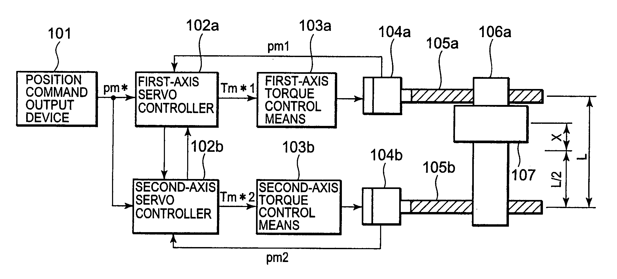
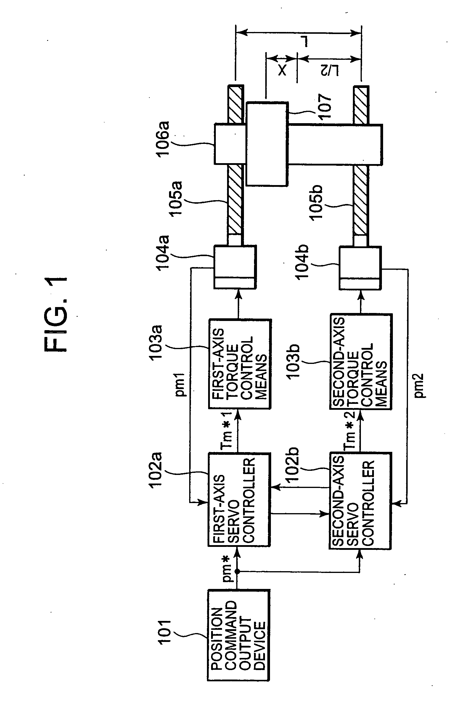
[0043] The configuration and operations of a biaxial driving machine will be described using FIG. 1.

[0044] A position command output device 101 outputs a position command pm* to a first-axis servo controller 102a and a second-axis servo controller 102b.

[0045] The first-axis servo controller 102a outputs a torque command Tm*1 to a first-axis torque control means 103a based on the position command pm* outputted by the position command output device 101 and an actual position pm1 of the first axis. The first-axis torque control means 103a controls a first-axis servomotor 104a in accordance with the torque command Tm*1.

[0046] The second-axis servo controller 102b outputs a torque command Tm*2 to a second-axis torque control means 103b based on the position command pm* outputted by the position command output device 101 and an actual position pm2 of the second axis. The second-axis torque control means 103b controls a second-axis servomotor 104b in accordance with the torque command T...

embodiment 2

[0085] The configuration and operations of the servo controller according to Embodiment 2 will be described according to FIG. 10, taking the first-axis servo controller 102a as an example.

[0086] The position command pm* outputted from the position command output device 101 (not illustrated) is inputted to a reference model control unit 1, which calculates and outputs a model position pa1, a model velocity wa1, and a model acceleration aa1.

[0087] A model torque correction unit 32a outputs a model torque Ta1 according to the model acceleration aa1, a first-axis actual position pm1 as the self-axis position, and a second axis actual position pm2 as the other-axis position.

[0088] The difference between the model position pa1 and the first axis actual position pm1 as the self-axis position is inputted from a subtracter 35 to a position control unit 34, which performs positional control, and outputs a velocity command.

[0089] A computing unit 37 adds the model velocity wa1 and the velo...

embodiment 3

[0117] The configuration and operations of a servo controller according to Embodiment 3 will be described according to FIG. 15, taking the first-axis servo controller 102a as an example. In FIG. 15, numerals 1 and 34 through 39 are the same as in FIG. 10, and the description thereof will be omitted.

[0118] The model torque correction unit 32b outputs the corrected model torque Ta1 based on the first-axis model acceleration aa1 outputted from the reference model control unit 1, and on the second-axis model acceleration aa2 outputted from the reference model control unit for the second-axis servo controller (not illustrated).

[0119] The servo controller according to Embodiment 3 is configured so that information on each other's model acceleration is exchanged. An example in which the second-axis model acceleration aa2 is used in the first-axis servo controller 102a has been described using FIG. 15.

[0120] The configuration and operations of the model torque correction unit 32b will be...


PUM


Abstract

In a servo controller according to the invention, a position feedback correction unit (3) calculates a first-axis position feedback signal (pmfb1) based on a first-axis position (pm1) as a self-axis position, and a second-axis position (pm2) as an other-axis position; and a deviation between a model position (pal) and the first-axis position feedback signal (pmfb1) is inputted from a subtracter (5) to a position control unit (4), which performs positional control to output a velocity command. A velocity feedback correction unit (6) calculates a first-axis velocity feedback signal (wmfb1) from a first-axis velocity (wm1) as the self-axis velocity, and a second-axis velocity (wm2) as the other-axis velocity; and the velocity control unit (8) adds a model velocity (wa1) and the velocity command outputted from the position control unit (5), and subtracts the first-axis velocity feedback signal (wmfb1) therefrom, and outputs a feedback torque command (Tfb1) based on the corrected velocity command.

Description

TECHNICAL FIELD [0001] The present invention relates to servo controllers for controlling the position of an electric motor as a load, and particularly to a servo controller that is applied to synchronous control of a multiaxial driving machine. BACKGROUND ART [0002] There has been a biaxial driving machine in which a moving table is supported by two ball screws disposed in parallel, and is driven by synchronously controlling two servomotors that are connected respectively to the two ball screws. The moving table in the biaxial driving machine installs, in general, an upper structure that is movable, and the center of gravity of the moving table varies according to the position of the upper structure, the load supported by the upper structure, and the like. [0003] Moreover, a position control device for a motor has been disclosed in Patent Document 1 (Japanese Patent Laid-Open No. 30578 / 1994) as related to position control devices for motors (direct-current motors, induction motors,...

Claims


Application Information

Patent Timeline
IPC IPC(8): H02P7/00B23Q15/00G05B13/04G05B19/18G05B19/19G05D3/00G05D3/12
CPCG05B2219/41205G05B19/19
Inventor TERADA, KEINAGANO, TETSUAKITAKAHASHI, KAZUTAKAISODA, TAKASHI
Owner MITSUBISHI ELECTRIC CORP
Why Eureka
Try Eureka