
Paper feeding device

A paper feeding device and paper feeding technology, which are applied in the directions of printing device, object supply, transportation and packaging, etc., can solve the problem of not being able to send out the paper regularly.

Active Publication Date: 2016-06-08
RISO KAGAKU CORP
View PDF8 Cites 7 Cited by
  • Summary
  • Abstract
  • Description
  • Claims
  • Application Information

AI Technical Summary

Problems solved by technology

Therefore, there are cases where the paper cannot be fed at the correct timing when the next sheet is fed from the paper feed deck.

Method used


Image

  • Paper feeding device
  • Paper feeding device
  • Paper feeding device

Examples


Embodiment Construction

[0035] Hereinafter, embodiments of the present invention are described with reference to the drawings. In addition, the same or similar reference numerals are assigned to the same or similar parts and components in the drawings, and descriptions of these parts or components are omitted or simplified. In addition, the drawings are schematic and therefore differ from actual ones.

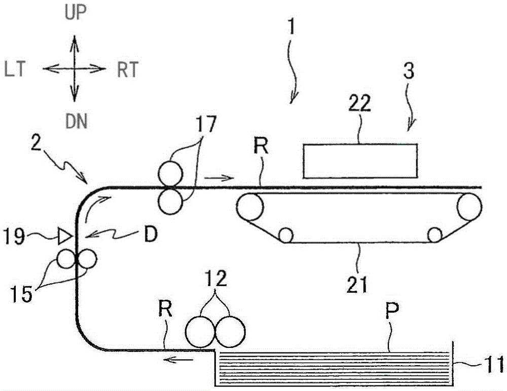
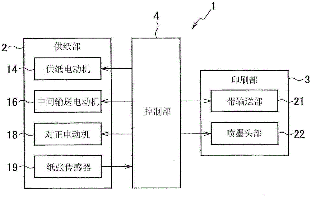
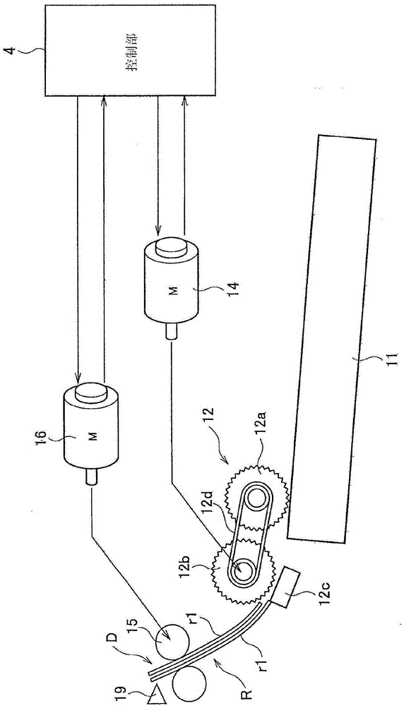
[0036] figure 1 is an explanatory diagram showing a schematic configuration of a printer including a paper feeding device according to an embodiment of the present invention, figure 2 yes means figure 1 A block diagram showing the structure of the printer's control system. In the instructions below, the figure 1 The direction perpendicular to the surface of the paper is defined as the front-rear direction, and the surface direction of the paper is defined as the front. exist figure 1 In , RT, LT, UP, and DN are used to represent right, left, up, and down, respectively. In addition, in figure ...


PUM


Abstract

A paper feeding device. A braking content determiner determines a content of braking control on a rotating operation such that rotation of a paper feeding motor stops within a time required for stopping from a time point of detection of a sheet by a sheet sensor to a time point of passing of a trailing edge of the sheet through a paper feeding roller, the time required for stopping being determined based on a length of the sheet in a sheet conveying direction, a predetermined speed of the paper feeding roller, and a distance between the paper feeding roller and the sheet sensor in a sheet conveying route. A controller performs the braking control on the rotating operation of the paper feeding motor, according to the content determined by the braking content determiner, upon or prior to the detection by the sheet sensor of the sheet sent out by the paper feeding roller.

Description

technical field [0001] The present invention relates to a paper feeding device for feeding paper. Background technique [0002] Printers such as inkjet printers and stencil printing devices have a paper feeding device that feeds paper from a paper feeding table to a printing unit. In such a paper feeding device, the paper sheets on the paper feeding table are fed out one by one to the intermediate conveying rollers by the paper feeding rollers, and then sent to the registration rollers by the intermediate conveying rollers. The front end of the fed paper comes into contact with the registration roller and stops temporarily. [0003] After the leading edge of the paper stops, the intermediate feed roller continues to feed the paper toward the registration roller side. Thus, slack is formed in the paper between the registration roller and the intermediate conveyance roller during the period before the registration roller starts to rotate. The slack is used to correct the sk...

Claims


Application Information

Patent Timeline
Patent Type & Authority Applications(China)
IPC IPC(8): B65H5/06B65H3/06
CPCB65H3/0638B65H5/06B65H2404/14B65H3/06B65H5/062B65H7/02B65H7/18B65H2511/11B65H2511/416B65H2511/514B65H2513/512B65H2701/1311B65H2403/725B65H2513/20B65H2515/10B65H2220/01B65H2220/02B65H2220/11B65H2403/00B41J13/076B65H3/0669B65H7/20
Inventor 井上英明
Owner RISO KAGAKU CORP
Learn More