
Valve timing control apparatus for internal combustion engine

a timing control and internal combustion engine technology, applied in mechanical equipment, valve arrangements, machines/engines, etc., can solve problems such as complicated positioning work related thereto, and achieve the effect of facilitating assembly work of each componen

Inactive Publication Date: 2014-05-08
HITACHI AUTOMOTIVE SYST LTD
View PDF1 Cites 7 Cited by
  • Summary
  • Abstract
  • Description
  • Claims
  • Application Information

AI Technical Summary

Benefits of technology

The present invention provides a valve timing control apparatus for an internal combustion engine that simplifies the assembly work of each component while reducing the deviation in position between the cover member and the phase modification mechanism.

Problems solved by technology

Therefore, a positioning work related thereto becomes complicated.

Method used


Image

  • Valve timing control apparatus for internal combustion engine
  • Valve timing control apparatus for internal combustion engine
  • Valve timing control apparatus for internal combustion engine

Examples


Embodiment Construction

[0019]Hereinafter, a preferred embodiment of a valve timing control apparatus for an internal combustion engine according to the present invention will be described on a basis of the attached drawings. It should be noted that this embodiment is applicable to a variably operated valve system at an intake side of the internal combustion engine. However, the present invention is similarly applicable to the variably operated valve system at an exhaust side of the internal combustion engine.

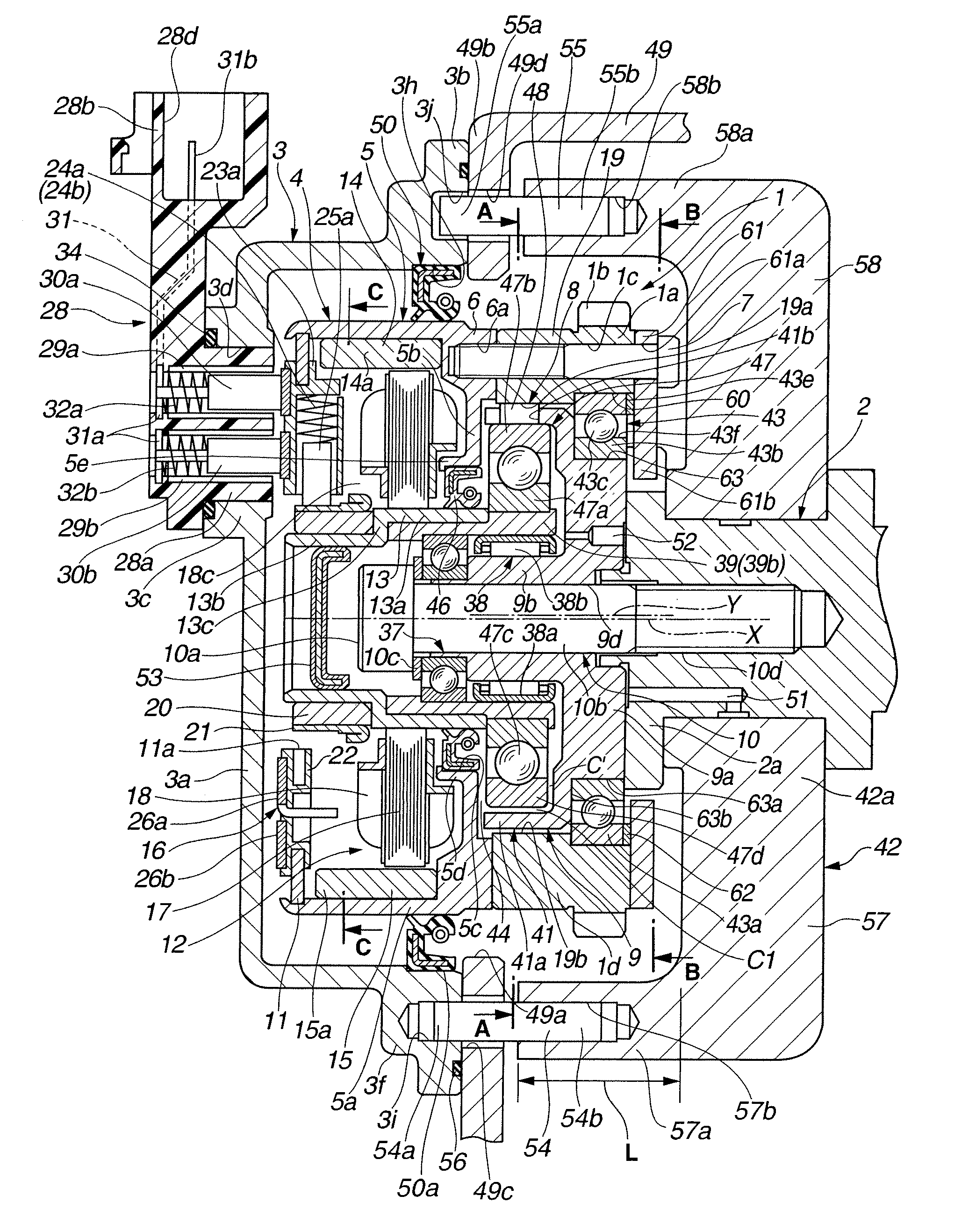
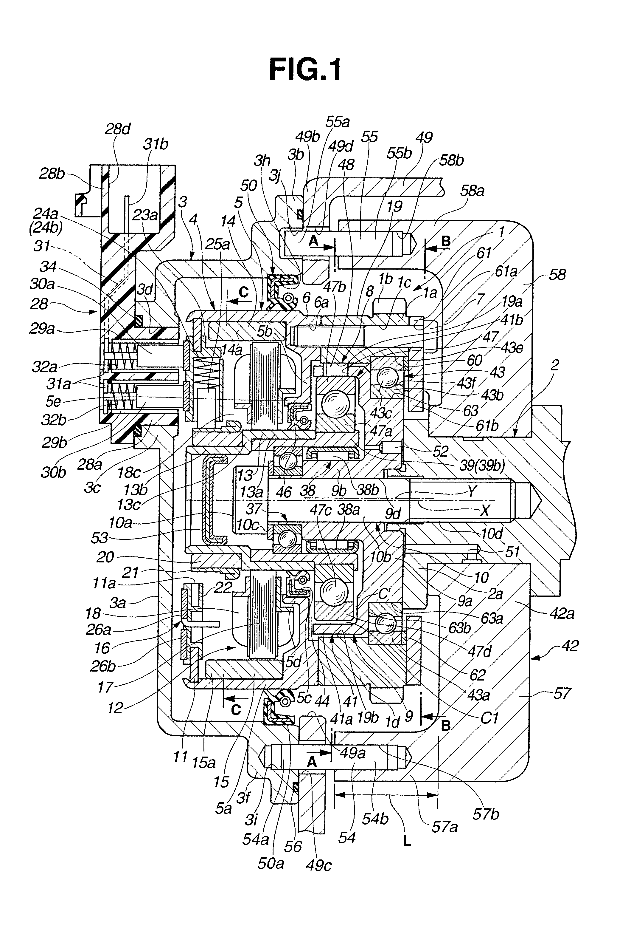
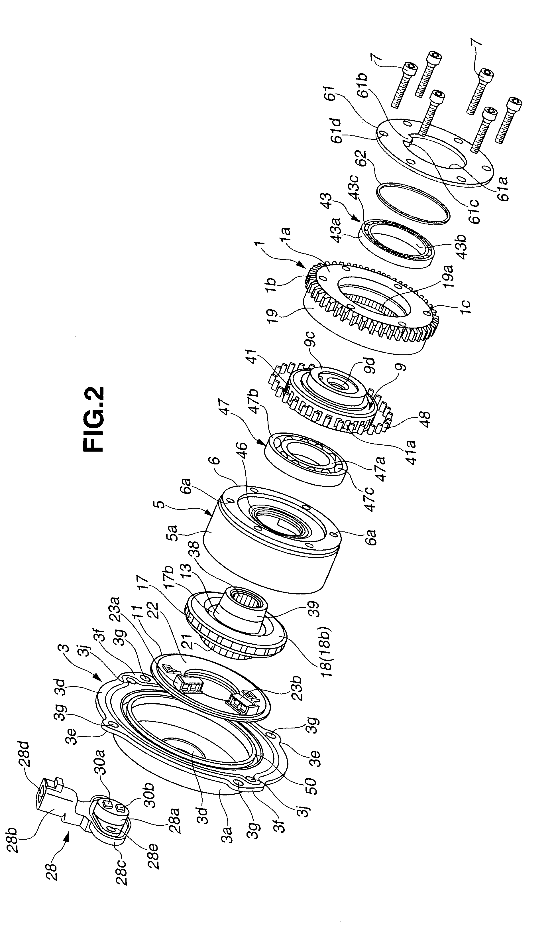
[0020]This valve timing control apparatus, as shown in FIGS. 1 and 2, includes: a timing sprocket 1 which is a driving rotary body rotatably driven by means of a crankshaft of the internal combustion engine; a camshaft 2 rotatably journalled by means of a bearing member 42 to installed on a cylinder head to rotate a rotational force transmitted from timing sprocket 1; a cover member 3 fixed by means of a chain cover 49 disposed on an outside of timing sprocket 1; and a phase modification mechanism 4 i...


PUM


Abstract

In a valve timing control apparatus for an internal combustion engine, a plurality of projection sections projected toward a cover member are integrally mounted on a bearing member configured to rotatably journalize a camshaft and a plurality of positioning pins are mounted across (or extended over) the cover member and the respective projection sections.

Description

BACKGROUND OF THE INVENTION[0001](1) Field of the Invention[0002]The present invention relates to a valve timing control apparatus for an internal combustion engine which controls valve open-and-closure characteristics of an intake valve(s) or an exhaust valve(s) of the internal combustion engine.[0003](2) Description of Related Art[0004]Recently, a valve timing control apparatus has been proposed in which a phase modification mechanism which converts a relative rotational phase of a camshaft with respect to a sprocket to which a rotational force from a crankshaft is transmitted by transmitting a rotational force of an electrically driven motor to a camshaft which provides an output axle via a speed reduction mechanism to control open-and-closure timings of an intake valve(s) and / or an exhaust valve(s).[0005]Such a valve timing control apparatus as described above is exemplified by a Japanese Patent Application First Publication No. 2011-256798 published on Dec. 22, 2011 in which a ...

Claims


Application Information

Patent Timeline
Patent Type & Authority Applications(United States)
IPC IPC(8): F01L1/344
CPCF01L1/344F01L2820/032
Inventor TADOKORO, RYONEMOTO, HIROYUKIYAMANAKA, ATSUSHI
Owner HITACHI AUTOMOTIVE SYST LTD
Learn More