Imaging apparatus and control method therefor

Active Publication Date: 2018-02-08
CANON KK
View PDF10 Cites 6 Cited by
  • Summary
  • Abstract
  • Description
  • Claims
  • Application Information

AI Technical Summary

Benefits of technology

[0004]The present invention provides an imaging apparatus that suppresses positional deviation

Problems solved by technology

However, as disclosed in Japanese Patent Application Laid-open No. 9-261526, if the image equivalent to one with along exposure time is obtained by using only a region with a sufficient exposure

Method used


Image

  • Imaging apparatus and control method therefor
  • Imaging apparatus and control method therefor
  • Imaging apparatus and control method therefor

Examples


first embodiment

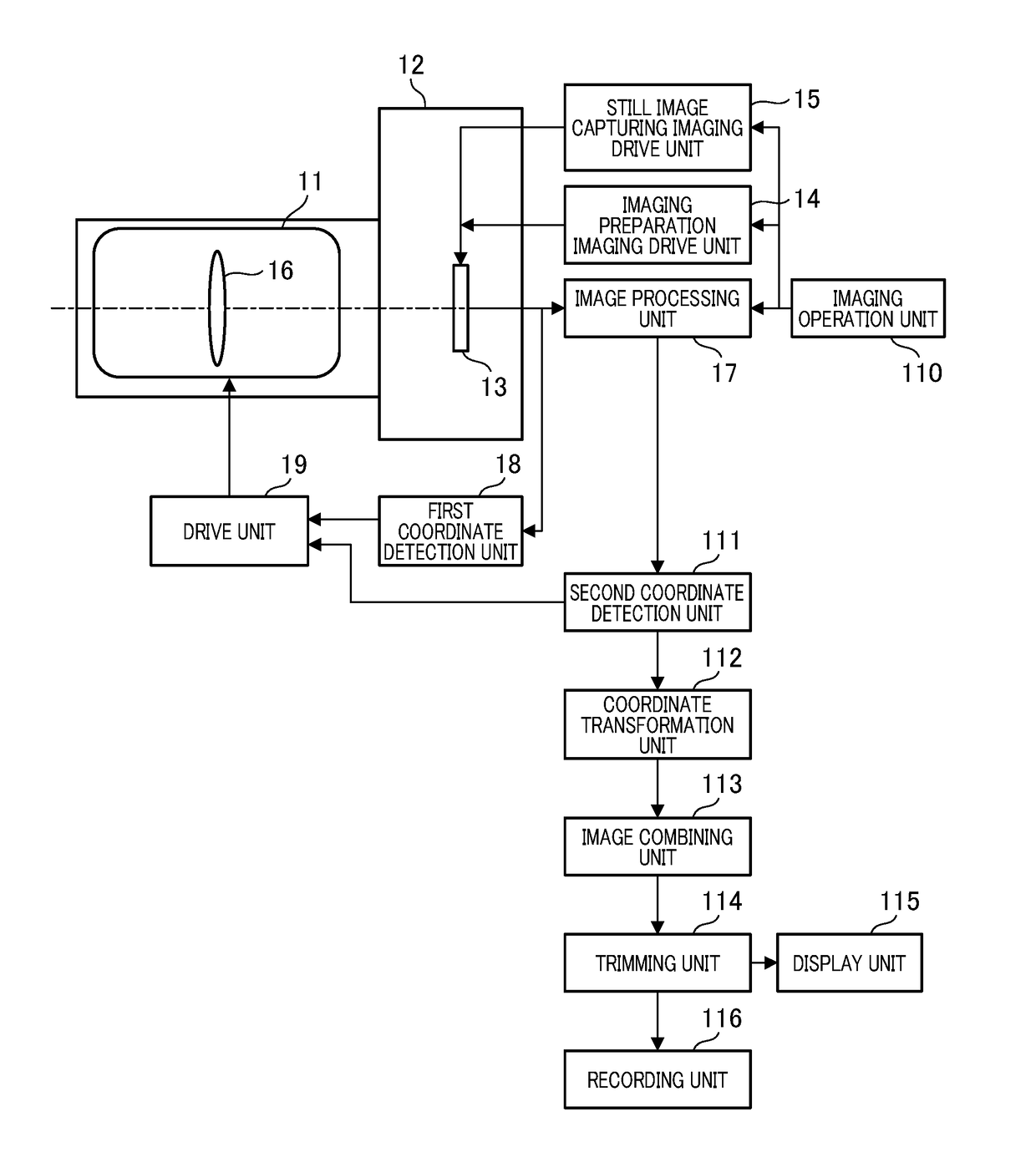
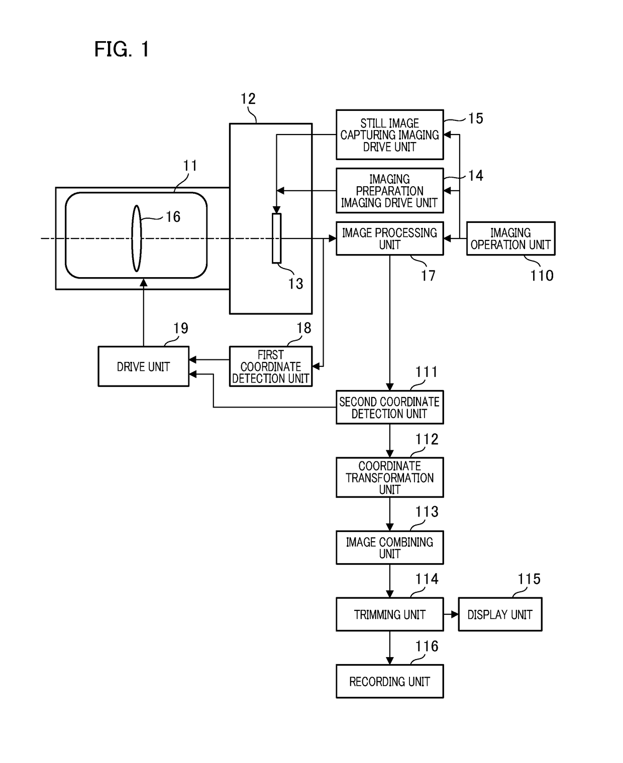
[0019]FIG. 1 is a block illustrating a configuration of an imaging apparatus. In the present embodiment, the imaging apparatus in which a camera body and a lens are integrated will be described as an example. However, the invention is not limited thereto, and a lens apparatus that is attachable and detachable to and from the camera body serving as an imaging apparatus may be used. The imaging apparatus according to the first embodiment includes an imaging optical system 11 serving as a lens and a camera body 12. The camera body 12 has, for example, an imaging unit 13 having an imaging element such as a CMOS image sensor and a CCD image sensor, a drive unit that drives and controls an imaging unit and the lens, a detection unit that detects coordinates from an image, a processing unit that performs an image process, and an image combining unit that performs image combining.

[0020]An imaging preparation imaging drive unit (preparation drive unit) 14 drives the imaging unit 13 for obser...

second embodiment

[0041]FIG. 6 is a block diagram illustrating a configuration of an imaging apparatus to which the second embodiment is applied. FIG. 6 is different from FIG. 1 in that a prediction unit 61 is provided. The prediction unit 61 predicts the next signal based on the current signal and the signal earlier than that signal. The prediction unit 61 is configured by a known technique such as a Kalman filter. The prediction unit 61 predicts the next coordinate signal based on the coordinate signals obtained from the first coordinate detection unit 18 and the second coordinate detection unit 111, and outputs the predicted result to the drive unit 19. The drive unit 19 drives the blur correction unit 16 based on the predicted result.

[0042]As described in the first embodiment, since the coordinate signals indicating the difference in composition between the continuous images are obtained after the image signals have been obtained, the coordinate signal is delayed by approximately one frame from t...

third embodiment

[0053]FIG. 11 is a block diagram illustrating a configuration of the imaging apparatus to which the third embodiment is applied. FIG. 11 is different from FIG. 6 in that an inter-frame coordinate detection imaging drive unit (inter-frame coordinate unit) 1101 is provided. The inter-frame coordinate unit 1101 drives the imaging unit 13 so as to obtain an inter-frame image to be used for coordinate detection of a difference in composition between the images while obtaining a plurality of still images for making a combined image.

[0054]In the first embodiment and the second embodiment, the first coordinate detection unit obtains the coordinate information for the difference in composition between the images from the image obtained for still images, and the drive unit 19 drives the blur correction unit 16 based on the information that has been obtained. In the third embodiment, the obtaining of an inter-frame image for obtaining the coordinate information is performed between the exposur...


PUM


Abstract

An imaging apparatus that performs positioning of a plurality of images that has been continuously captured and combines the images comprises an imaging unit; a detection unit configured to detect a difference in position between the images captured by the imaging unit; a drive unit configured to drive a shake correction unit that optically corrects image blur of the image based on the difference in position detected by the detection unit; a coordinate transformation unit configured to perform positioning of the images in which the image blur has been corrected based on the difference in position detected by the detection unit; and an image combining unit configured to combine the images to which the positioning has been performed by the coordinate transformation unit and generate a combined image.

Description

BACKGROUND OF THE INVENTIONField of the Invention[0001]The present invention relates to an imaging apparatus and a control method therefor.Description of the Related Art[0002]In order to suppress the influence of image blur due to hand shaking and the like during camera hand-held shooting, there is a conventional technique that generates an image having a sufficient exposure in which image blur is suppressed by shooting and combining a plurality of images with a short exposure time at which image blur appears with difficulty. Japanese Patent Application Laid-Open Publication No. 9-261526 discloses an image combining and anti-shake technique that obtains an image equivalent to an image with a long exposure time in which image blur is suppressed by performing positioning of a plurality of images captured in a short time and combining the images.[0003]However, as disclosed in Japanese Patent Application Laid-open No. 9-261526, if the image equivalent to one with along exposure time is ...

Claims


Application Information

Patent Timeline
IPC IPC(8): H04N5/265H04N5/374G06T5/00H04N5/232
CPCH04N5/265H04N5/23254H04N5/23267G06T2207/20201G06T5/003G06T2207/20132H04N5/374G06T5/50G06T2207/20221H04N23/60H04N23/6811H04N23/6845H04N23/683H04N25/76
Inventor KAJIMURA, FUMIHIROWASHISU, KOICHI
Owner CANON KK
Why Eureka
Try Eureka