Current sensor

a current sensor and sensor technology, applied in the direction of measuring instrument housings, coupling device connections, instruments, etc., can solve the problems of high possibility of gap formation within the housing, no pressing force can be applied between the bus bar and the circuit board, and the possibility of gap formation is high, so as to suppress the positional misalignment

Active Publication Date: 2019-06-20
HITACHI METALS LTD
View PDF0 Cites 6 Cited by
  • Summary
  • Abstract
  • Description
  • Claims
  • Application Information

AI Technical Summary

Benefits of technology

[0013]According to the present invention, it is possible to provide the current sensor capable of suppressing the positional misalignment between the bus bar and the magnetic detection element.

Problems solved by technology

However, in the above current sensor, when the upper and lower housings are in contact with each other in the plate thickness direction, a gap forms within the housings due to manufacturing tolerance and the like, and no sufficient pressing force may be applied to between the bus bar and the circuit board.
This is because the plurality of the members such as the bus bar, the circuit board, the spacer, the upper and lower housings, etc. are stacked, therefore the influences of the tolerances of each member accumulate, leading to the high possibility of the gap formation within the housings.
In this case, however, when the upper and lower housings are fixed together by bolt fixation or the like, the housings may be dented and deformed in the gap portion.

Method used


Image

  • Current sensor
  • Current sensor
  • Current sensor

Examples


embodiment

[0027]An embodiment of the present invention will be described below with reference to the accompanying drawings.

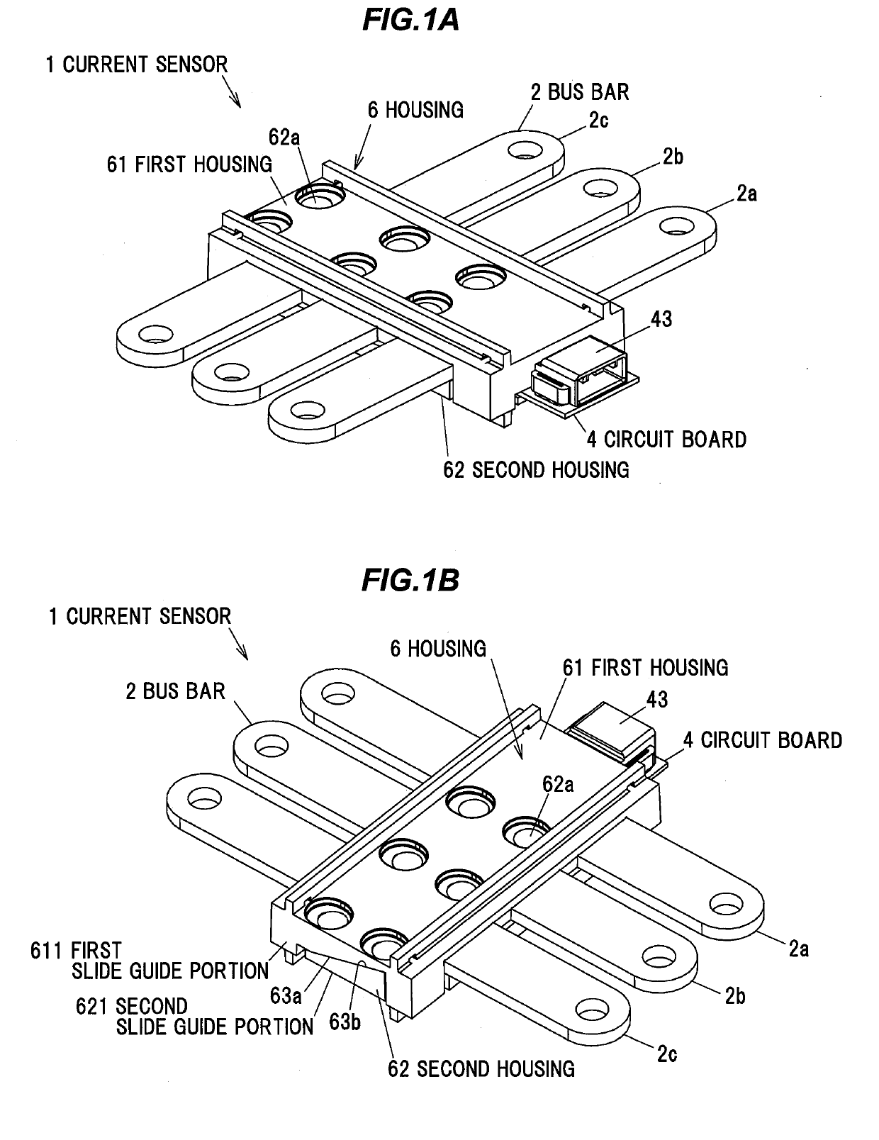
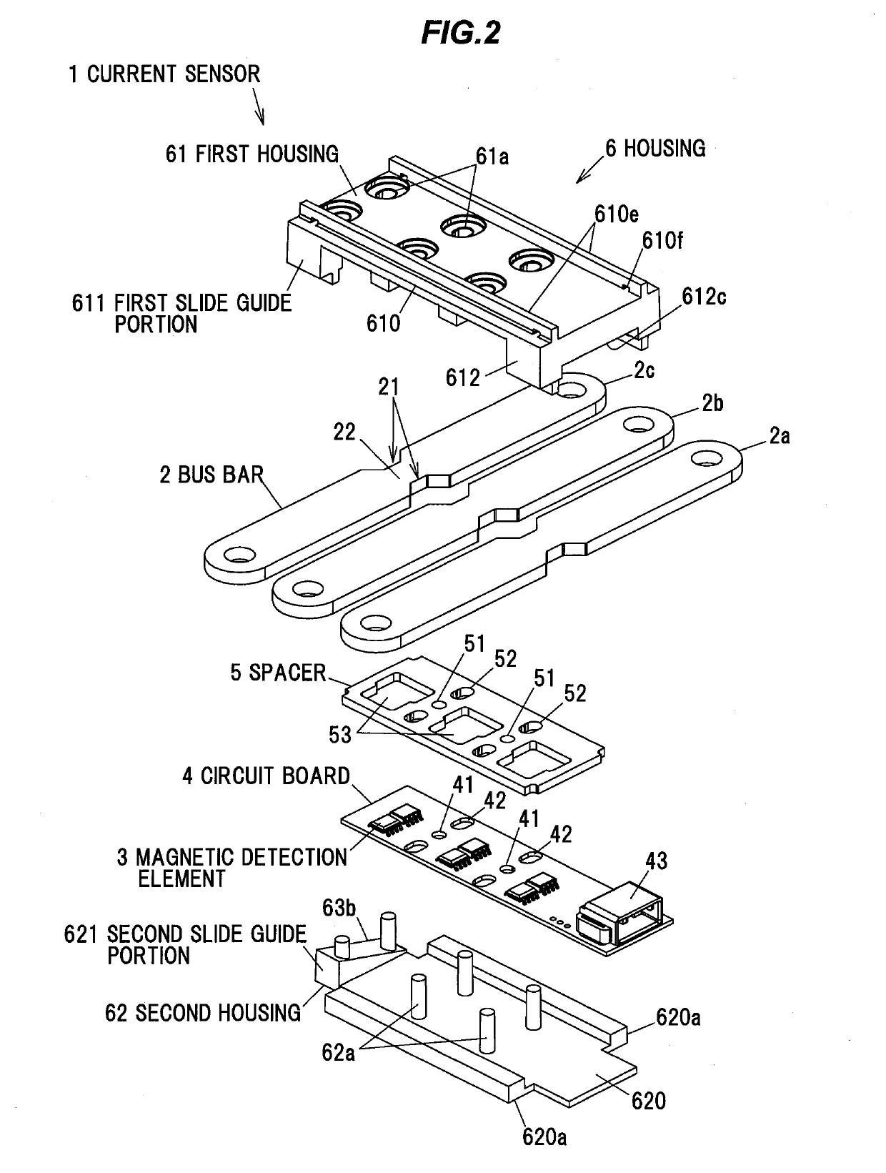
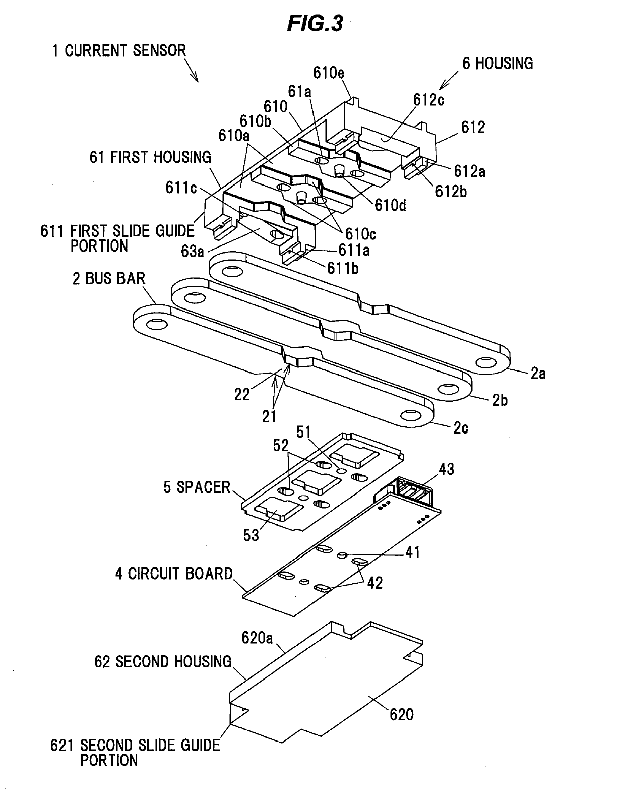
[0028]FIGS. 1A and 1B are perspective views showing a current sensor according to one embodiment of the present invention. FIGS. 2 and 3 are exploded perspective views of the current sensor.

[0029]As shown in FIGS. 1A to 3, the current sensor 1 includes a bus bar 2 in which a current to be detected flows, a magnetic detection element 3, a circuit board 4 on which the magnetic detection element 3 is mounted, a spacer 5, and a housing 6 having a structure divided into two halves: a first housing 61 and a second housing 62. Note that in FIGS. 1A to 3, a shield plate 7 to be described later is omitted (see FIG. 7).

[0030](Explanation of Bus Bar 2)

[0031]The bus bar 2 is a plate-like conductor made of a good electric conductor such as copper or aluminum, and serves as an electric current path in which electric current flows. The bus bar 2 is for use as, e.g., a power supply line ...


PUM


Abstract

A current sensor includes a bus bar in which a current to be detected flows, a circuit board mounted with a magnetic detection element thereon to detect a strength of a magnetic field generated by a current flowing in the bus bar, and a housing including first and second housings provided in such a manner as to sandwich the bus bar and the circuit board therebetween in a plate thickness direction of the bus bar. The first and second housings include slide guide portions respectively which are relatively slidable in a sloping direction with respect to the plate thickness direction of the bus bar while abutting each other in the plate thickness direction of the bus bar.

Description

CROSS-REFERENCE TO RELATED APPLICATION[0001]The present application is based on Japanese patent application No. 2017-240048 filed on Dec. 14, 2017, the entire contents of which are incorporated herein by reference.BACKGROUND OF THE INVENTION OF THE INVENTION1. Field of the Invention[0002]The present invention relates to a current sensor.2. Description of the Related Art[0003]Conventionally, there is known a current sensor including a magnetic detection element for detecting the strength of a magnetic field generated by a current to be measured. By detecting the strength of the magnetic field by the magnetic detection element, it is possible to calculate the current based on the strength of the magnetic field. As the current sensor of this type, there is known one in which a bus bar serving as a current path and a magnetic detection element are covered with a housing (see, e.g., JP-A-2017-102024).[0004]In the current sensor, it is desirable to minimize the positional misalignment of ...

Claims


Application Information

Patent Timeline
Patent Type & Authority Applications(United States)
IPC IPC(8): G01R19/00G01R1/04G01R15/20H01R25/16
CPCG01R19/0092G01R1/04G01R15/207H01R25/16G01R15/20G01R15/202G01R15/205G01R15/148G01R33/02G01R31/315G01N27/83G01N27/82G01N27/9046G01N17/02
Inventor UMETSU, JUNFUTAKUCHI, NAOKIKOMANO, HARUYASUOKUYAMA, KENTOMITA, YUJIRO
Owner HITACHI METALS LTD
Why Eureka
Try Eureka