Communication system, transmitter and receiver

a communication system and transmitter technology, applied in the field of communication systems, can solve problems such as non-real-time data exchang

Inactive Publication Date: 2006-08-24
NTT DOCOMO INC
View PDF8 Cites 48 Cited by
  • Summary
  • Abstract
  • Description
  • Claims
  • Application Information

AI Technical Summary

Benefits of technology

[0016] Moreover, for the communication system of the first aspect, the parameter adjuster may provide a value for the window size, the delay, and the maximum transmission count for the data type of non-real time are greater than the value provided for the data type of real time.
[0026] As described above, according to the present invention, it is possible to provide a communication system in which appropriate retransmission control operations can be applied to two data types including real time data and non-real time data, and a transmitter and a receiver used for this communication system.

Problems solved by technology

However, non-real time data exchanged by the PS and real time data exchanged as packets using the VoIP technique have opposing characteristics.

Method used


Image

  • Communication system, transmitter and receiver
  • Communication system, transmitter and receiver
  • Communication system, transmitter and receiver

Examples


first embodiment

(Transmitter)

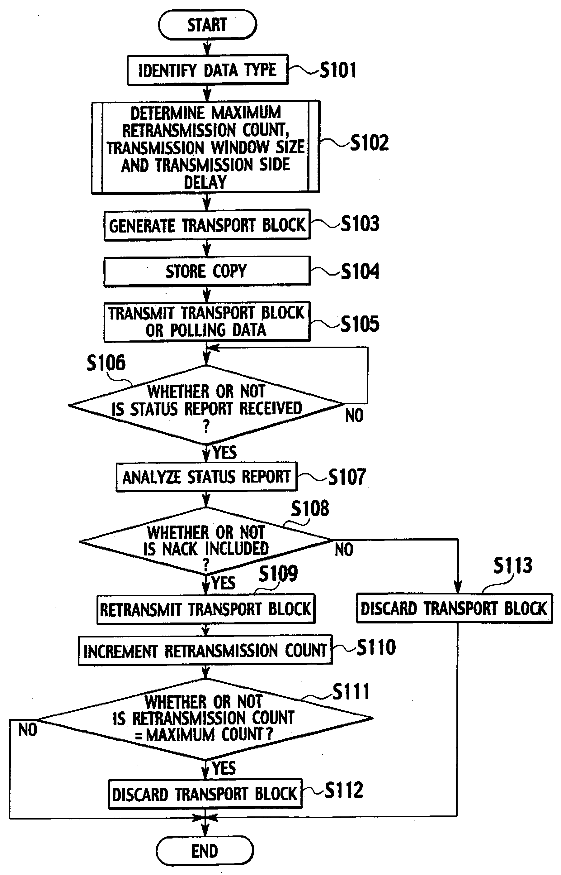
[0046] An explanation will now be given for a case in which the base stations 200 transmit data to the mobile stations 300, i.e., the base stations 200 serve as transmitters.

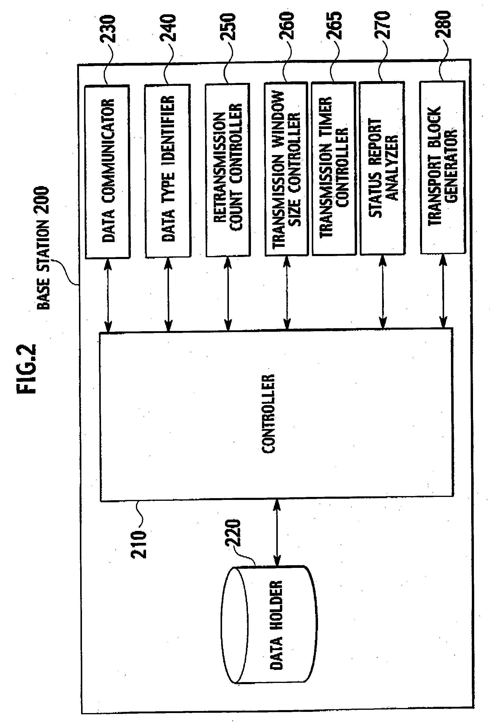
[0047] As shown in FIG. 2, each of the base stations 200 includes: a controller 210, a data holder 220, a data comunicator 230, a data type identifier 240, a retransmission count controller 250, a transmission window size controller 260, a transmission timer controller 265, a status report analyzer 270 and a transport block generator 280.

[0048] The controller 210 controls all the other components, and the operation of the entire base station 200. The controller 210 also serves as a parameter adjuster that employs a data type to adjust parameters used by the retransmission count controller 250, the transmission window size controller 260 and the transmission timer controller 265, which will be described later. Non-real time data tolerates delays, to a certain degree, but not data errors. On the o...

second embodiment

(Transmitter)

[0151] An explanation will now be given for data transmissions by base stations 200 to mobile stations 300, i.e., a case in which the base stations 200 serve as transmitters.

[0152] Since the base stations 200 according to this embodiment have the same configuration as the base stations 200 in the first embodiment, an explanation will be given only for a status report analyzer 270, which is a constituent feature having a different function from that in the first embodiment.

[0153] The status report analyzer 270, as in the first embodiment, analyzes a status report to determine whether or not a transport block has been correctly received. However, the status report analyzer 270 of this embodiment also determines whether or not the status report itself has been correctly received.

[0154] In this embodiment, redundant data, such as a CRC (Cyclic Redundancy Code), that enables error detection is provided for a status report transmitted by the mobile station 300. The statu...

third embodiment

(Transmitter)

[0185] An explanation will now be given for data transmission by base stations 200 to mobile stations 300, i.e., a case in which the base stations 200 serve as transmitters.

[0186] The base stations 200 in this embodiment have the same configuration as the base stations 200 in the first embodiment. Accordingly, an explanation will be given only for a status report analyzer 270 which is a constituent feature having a different function from that in the first embodiment.

[0187] The status report analyzer 270, as well as the status report analyzer 270 in the first embodiment, analyzes a status report to determine whether or not a transport block has been correctly received.

[0188] It should be noted, however, that in this embodiment the mobile station 300 repetitively transmits the status report for a predetermined number of times (RN). Therefore, when the status report analyzer 270 obtains, via a data comunicator 230, a status report that has the same contents for RN ti...


PUM


Abstract

Disclosed is a communication system in which appropriate retransmission control operations are respectively performed for two data types including real time data and non-real time data, and the transmitter and the receiver used for this communication system. A data type identifier identifies a data type as real time or non-real time, and based on the identified data type, a controller, and another controller (not shown) adjust parameters used for retransmission control.

Description

BACKGROUND OF THE INVENTION [0001] 1. Field of the Invention [0002] The present invention relates to a communication system in which a transmitter transmits two types of data including real time data and non-real time data to a receiver. The present invention also relates to the transmitter and the receiver used for this communication system. [0003] 2. Related Background Art [0004] Conventionally, for a communication system in which a transmitter transmits data to a receiver, when a communication error occurs, a retransmission control technique has been employed. In the retransmission control technique, the receiver requires the transmitter to retransmit data which has caused an error, thus selectively correcting this data. For example, a technique using the retransmission control technique while taking QoS (Quality of Service) into account has been disclosed (for example, refer to Japanese Patent Laid-open Official Gazette No. 2002-271366). [0005] Furthermore, according to an HSDPA...

Claims


Application Information

Patent Timeline
Patent Type & Authority Applications(United States)
IPC IPC(8): G06F15/16H04L47/2416H04L47/27H04W28/00H04W28/04
CPCH04L1/007H04L1/1812H04L1/1877H04L2001/0098G04G9/04A44C5/12
Inventor MOTEGI, MASAYUKITAKAHASHI, HIDEAKIKATO, YASUHIRONAKAMURA, TAKEHIRO
Owner NTT DOCOMO INC
Why Eureka
Try Eureka