Transaction flow control mechanism for a bus bridge

Inactive Publication Date: 2006-08-24
GOOGLE LLC
View PDF60 Cites 12 Cited by
  • Summary
  • Abstract
  • Description
  • Claims
  • Application Information

AI Technical Summary

Benefits of technology

[0014] The present invention provides a bus bridge for a high speed computer processor system with a high speed interface for a graphics processor. The invention provides a bus bridge between a GPUL bus

Problems solved by technology

Without a higher speed interface connection the computer gaming industry will not be abl

Method used


Image

  • Transaction flow control mechanism for a bus bridge
  • Transaction flow control mechanism for a bus bridge
  • Transaction flow control mechanism for a bus bridge

Examples


Embodiment Construction

Bus Overview

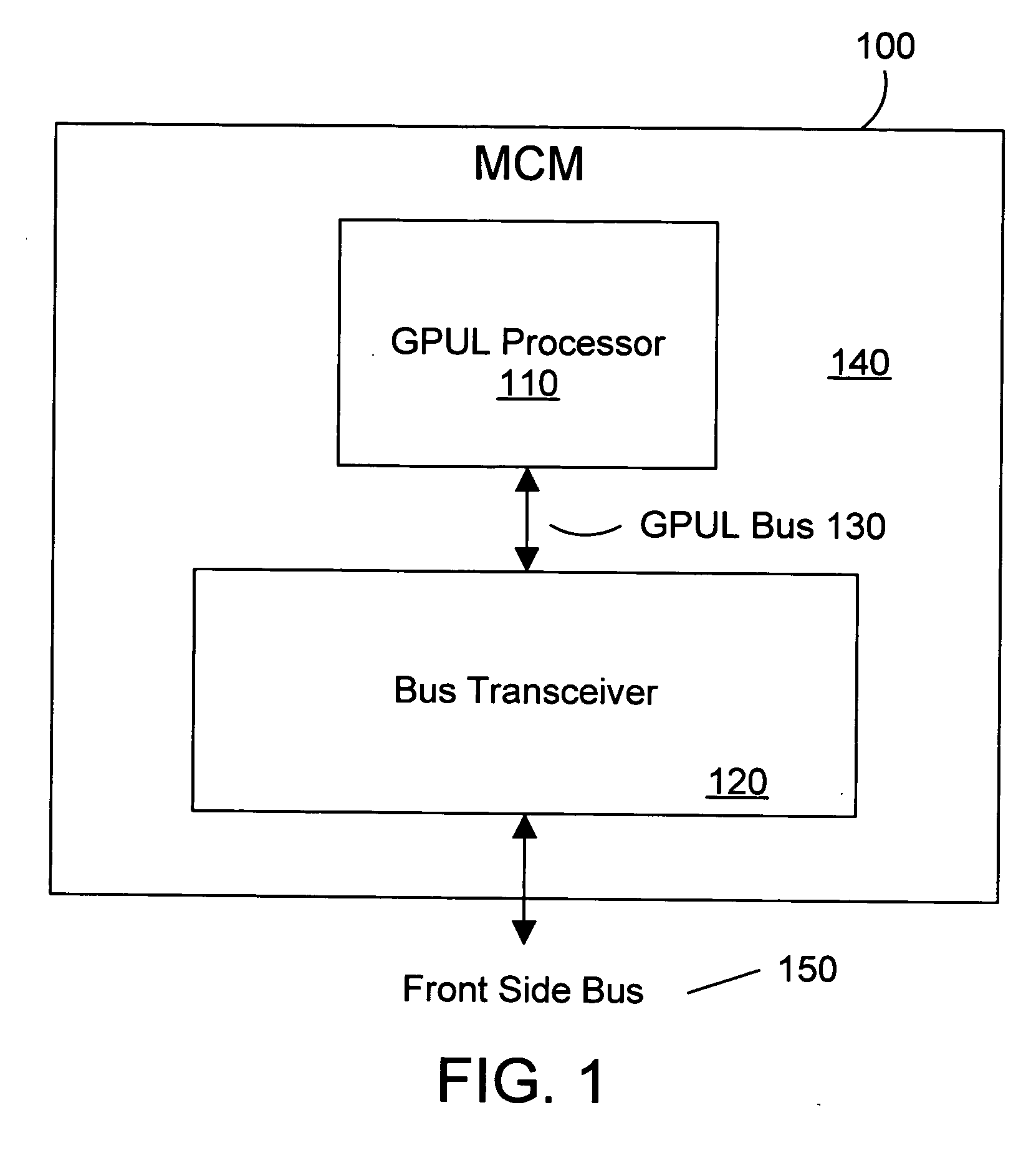
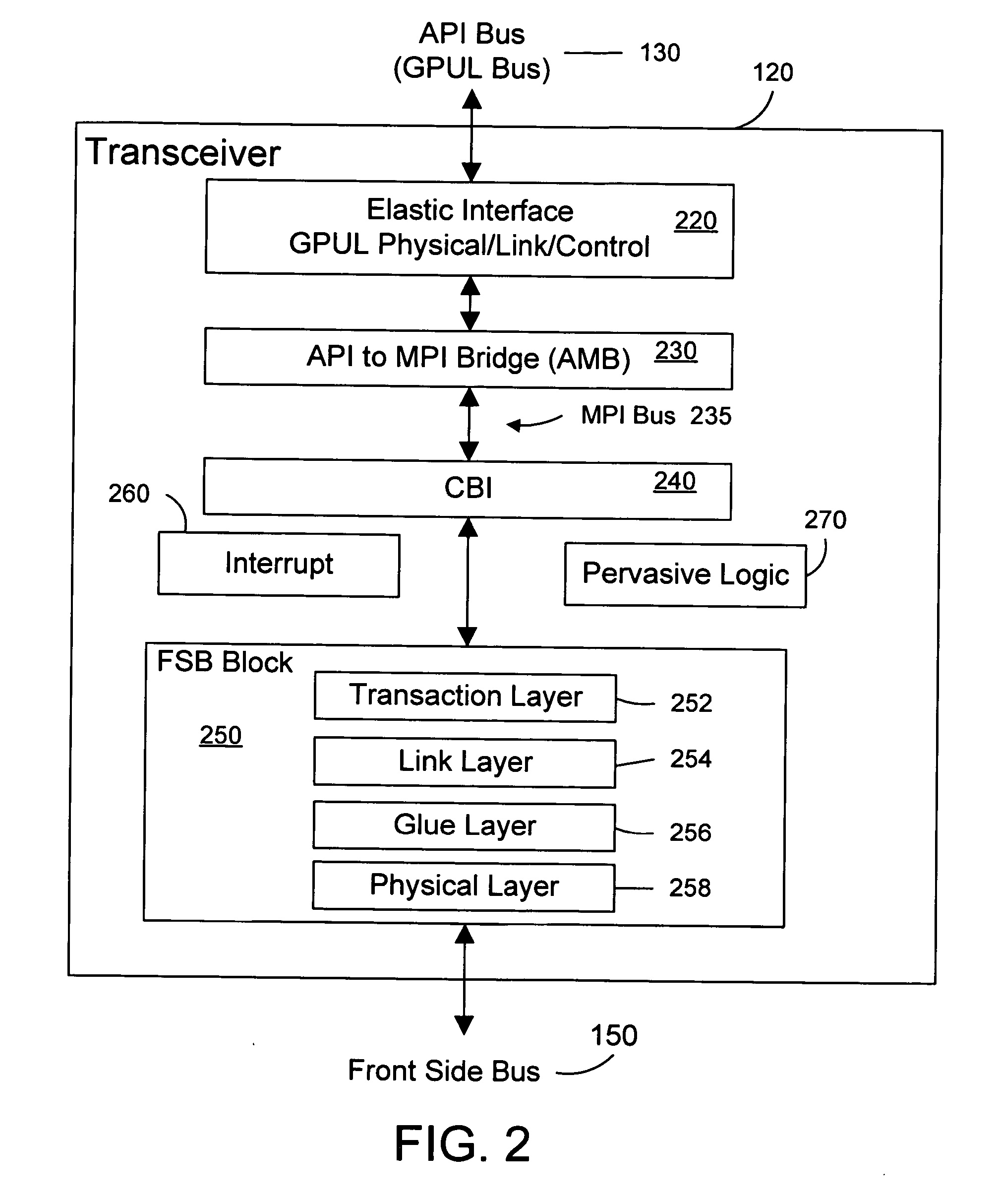
[0032] The present invention provides a bus bridge between two high speed computer buses. The preferred embodiment is a bus bridge between a GPUL bus for a GPUL PowerPC microprocessor from International Business Machines Corporation (IBM) and an output high speed interface (MPI bus). Published information is available about the GPUL processor 110 and the GPUL bus 130 from various sources including IBM's website. This section provides an overview of these two buses.

API Bus

[0033] The API bus is sometimes referred to as the PowerPC 970FX interface bus, GPUL Bus or the PI bus (in the PowerPC's specifications). This document primarily uses the term API bus, but the other terms are essentially interchangeable. The API bus consists of a set of unidirectional, point-to-point bus segments for maximum data transfer rates. No bus-level arbitration is required. An Address / Data (AD) bus segment, a Transfer Handshake (TH) bus segment, and a Snoop Response (SR) bus segment exist i...


PUM


Abstract

A transaction flow control mechanism is disclosed for a bus bridge in a high speed computer system with a high speed interface for a graphics processor. A preferred embodiment provides a flow control mechanism for the bus bridge between a GPUL bus for a GPUL PowerPC microprocessor from International Business Machines Corporation (IBM) and a high speed interface. A preferred embodiment of the invention is a bus transceiver on a multi-chip module.

Description

RELATED APPLICATIONS [0001] The present application is related to the following applications, which are incorporated herein by reference: [0002]“Method and System for Ordering Requests at a Bus Interface”, Ogilvie et al., Ser. No. ______, co-filed herewith (IBM Docket No. ROC920040299US1); [0003]“Data Ordering Translation Between Linear and Interleaved Domains at a Bus Interface”, Horton et al., Ser. No. ______, co-filed herewith (IBM Docket No. ROC920040300US1); [0004]“Method and System for Controlling Forwarding or Terminating of a Request at a Bus Interface Based on Buffer Availability”, Ogilvie et al., Ser. No. ______, co-filed herewith (IBM Docket No. ROC920040301US1); [0005]“Computer System Bus Bridge”, Biran et al., Ser. No. ______, co-filed herewith (IBM Docket No. ROC920040302US1); [0006]“Apparatus and Method for Transaction Tag Mapping Between Bus Domains”, Kautzman et al., Ser. No. ______, co-filed herewith (IBM Docket No. ROC920040303US1); [0007]“Pipeline Bit Handling Ci...

Claims


Application Information

Patent Timeline
IPC IPC(8): G06F13/36
CPCG06F13/4059G06F12/0831
Inventor OGILVIE, CLARENCE ROSSERWOODRUFF, CHARLES S.
Owner GOOGLE LLC
Why Eureka
Try Eureka