Closure cap and combination of a closure cap and a receiving vessel

a technology of closure cap and receiving vessel, which is applied in the direction of drinking vessels, liquid dispensing, containers, etc., can solve the problems of not being able to provide a rotary closure cap with a central axis, and achieve the effects of reducing the diameter, preventing abrasion, and facilitating the mounting of the holding pla

Inactive Publication Date: 2006-08-31
ALPLA WERKE ALWIN LEHNER
View PDF6 Cites 3 Cited by
  • Summary
  • Abstract
  • Description
  • Claims
  • Application Information

AI Technical Summary

Benefits of technology

[0008] On account of this configuration, the orientation and association of closure stopper and mouthpiece opening are ensured and simplified during fitting of the closure cap onto the mouthpiece opening region of the bottle vessel. Any manufacturing tolerances can be compensated for by the closure stopper being disposed pivotably. In particular, an eccentrically disposed mouthpiece opening can be reliably closed off via the closure stopper by means of the closure cap according to the invention. The rotary-alignment part serves to automatically direct the closure stopper into the position of association with respect to the mouthpiece opening.
[0009] In this respect, similar aspects also apply in regard to the subject matter of the closure cap. Therefore, the closure stopper, during fitting of the closure cap onto the bottle vessel, is forcibly displaced, by means of the rotary-alignment part, which furthermore is preferably disposed such that it rotates with the closure stopper in the closure cap, into the association position. In a preferred configuration, the closure stopper is formed on a holding plate which is disposed such that it can rotate relative to the cap base and is mounted rotatably, in the manner of a disk, around a central axis of rotation of the closure cap. The closure stopper and the associated mouthpiece opening may be disposed centrally. The invention has proven particularly advantageous in a configuration in which the closure stopper and the mouthpiece opening are disposed eccentrically relative to a central axis of rotation of the closure cap. On account of the closure stopper being disposed pivotably in accordance with the invention, therefore, even a mouthpiece opening of the bottle vessel that is disposed eccentrically with respect to the central axis of rotation of the closure cap can be reliably closed by the closure stopper on the cap side. On account of the configuration according to the invention, it is also possible to achieve a more reliable closure of a multicomponent bottle vessel having a corresponding plurality of mouthpiece openings, in which case one central mouthpiece opening may also be associated with one or more eccentrically disposed mouthpiece openings. Therefore, it is furthermore proposed that two oppositely-disposed closure stoppers, with rotary-alignment parts located between them in the direction of rotation, are disposed on the holding plate. A configuration in which the closure stoppers and accordingly also the mouthpiece openings are disposed diametrically opposite is preferred. Each closure stopper can be associated with one mouthpiece opening of the bottle vessel. It is also conceivable for more than two closure stoppers to be disposed for the purpose of closing off a corresponding number of mouthpiece openings. The rotary-alignment part disposed between the closure stoppers is used to automatically orientate the holding plate and, by means of this, the closure stoppers during fitting of the closure cap onto the bottle vessel. The preferably disk-like holding plate may be held on the cap base at the boundary side. It is also conceivable for the holding plate to be seated on a latching pin which is formed on the cap base and preferably disposed centrally, which latching pin at the same time forms the body axis of rotation for the holding plate. In particular in the case of a holding plate which is formed with a reduced diameter compared to the cap base, it is also provided that centering formations be formed on the cap base to facilitate mounting of the holding plate. Furthermore, it is preferable for the centering formations and the latching pin to be formed integrally, from the same material, on the cap base. In its most simple form, the closure cap according to the invention may be formed as a press-fit cap with a self-aligning closure stopper. A configuration in which the closure cap is a screw cap is preferred. As the cap is being screwed on, the rotary-alignment parts are responsible for orientating the position of the closure stoppers with respect to the mouthpiece openings. The solution according to the invention has also proven advantageous for a configuration with just one central mouthpiece opening. The stopper, which has been displaced axially towards the mouthpiece opening as the cap is being screwed on, is held frictionally on the mouthpiece wall. The further displacement of the cap as it is being screwed on then merely effects a linear displacement of the stopper into the opening. This counteracts any abrasion in this region of interaction.
[0010] Furthermore, the invention relates to a combination of a closure cap, which is preferably produced using the plastics injection molding process and has a closure stopper, and a receiving vessel, preferably a bottle, which has at least one mouthpiece opening, which preferably likewise consists of plastics and is formed eccentrically with respect to a central axis of rotation of the closure cap, the closure cap having a cap base, and the closure stopper being formed on the inner side of the cap base, facing the mouthpiece opening. To make such a combination of closure cap and receiving vessel more functionally reliable, in particular with regard to the closure of the mouthpiece opening, it is proposed that the closure stopper is disposed such that it can pivot relative to the cap base in a plane that is parallel to the cap base, and that the mouthpiece opening is formed such that it is raised up with respect to a surrounding vessel cover of the receiving vessel. The mouthpiece opening of the receiving vessel is disposed in a central region, which is elevated with respect to the vessel cover, although the mouthpiece opening does not necessarily have to be disposed centrally, but rather may also be disposed eccentrically with respect to a vessel cover center axis. It is also provided that the rotary-alignment part is formed on an arc of a circle which intersects the closure stopper or mouthpiece opening. On account of this configuration, automatic alignment of the cap-side closure stopper with respect to the mouthpiece opening is achieved while the closure cap is being attached. Therefore, it is further provided that the closure cap is held on the discharge vessel by means of a screw closure, and that the screw closure is not (yet) active when the rotary-alignment part collides with the mouthpiece opening. On account of this configuration, the screw closure can be made to become active only once the closure stopper has been oriented in a deliberate way with respect to the mouthpiece opening. Finally, it is provided that when the closure cap has been screwed on, the rotary-alignment part is disposed above the vessel cover and laterally with respect to the mouthpiece opening formation.

Problems solved by technology

From this, it is not however already known to provide a rotary closure cap with a central axis of rotation.

Method used


Image

  • Closure cap and combination of a closure cap and a receiving vessel
  • Closure cap and combination of a closure cap and a receiving vessel
  • Closure cap and combination of a closure cap and a receiving vessel

Examples


first embodiment

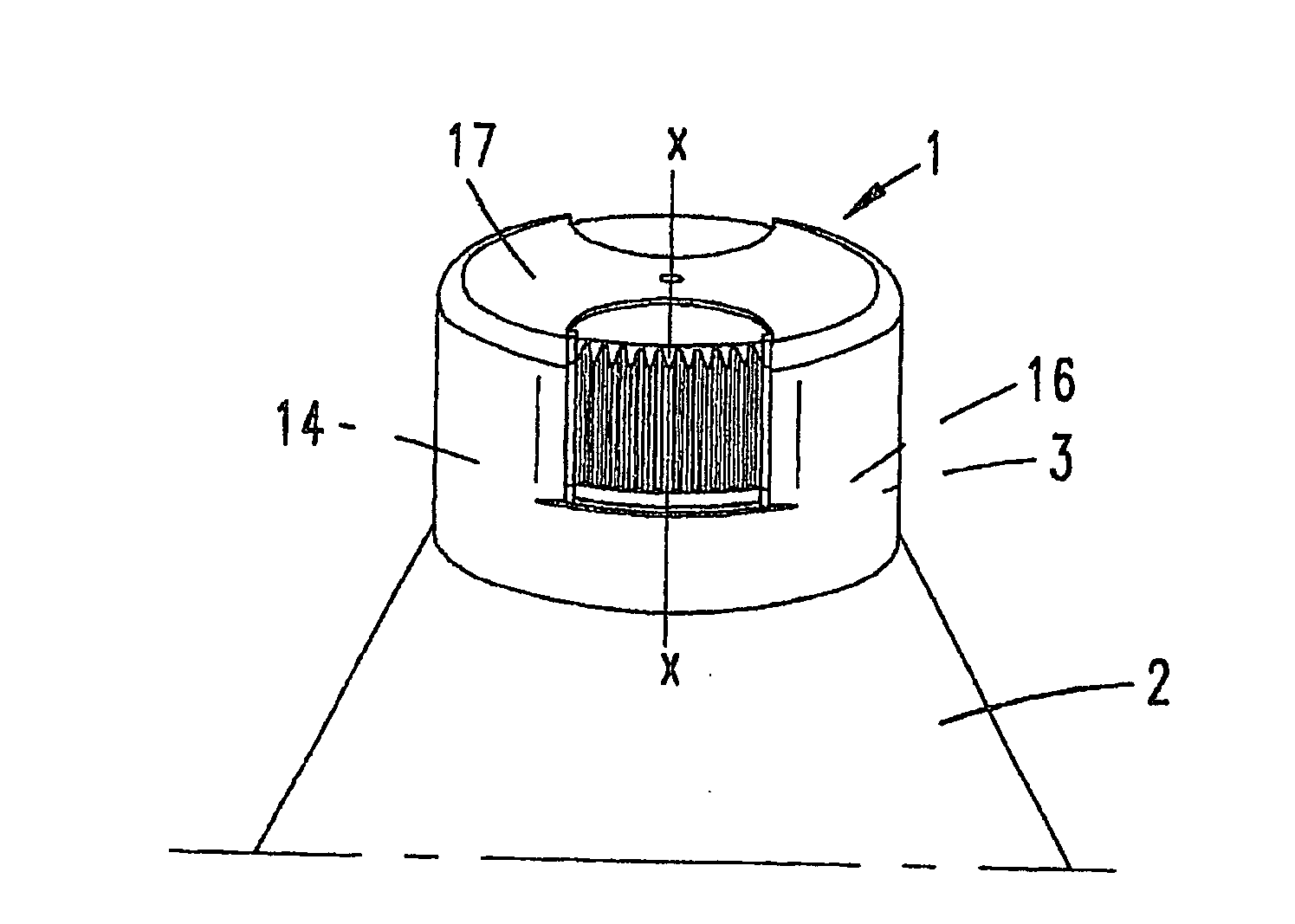
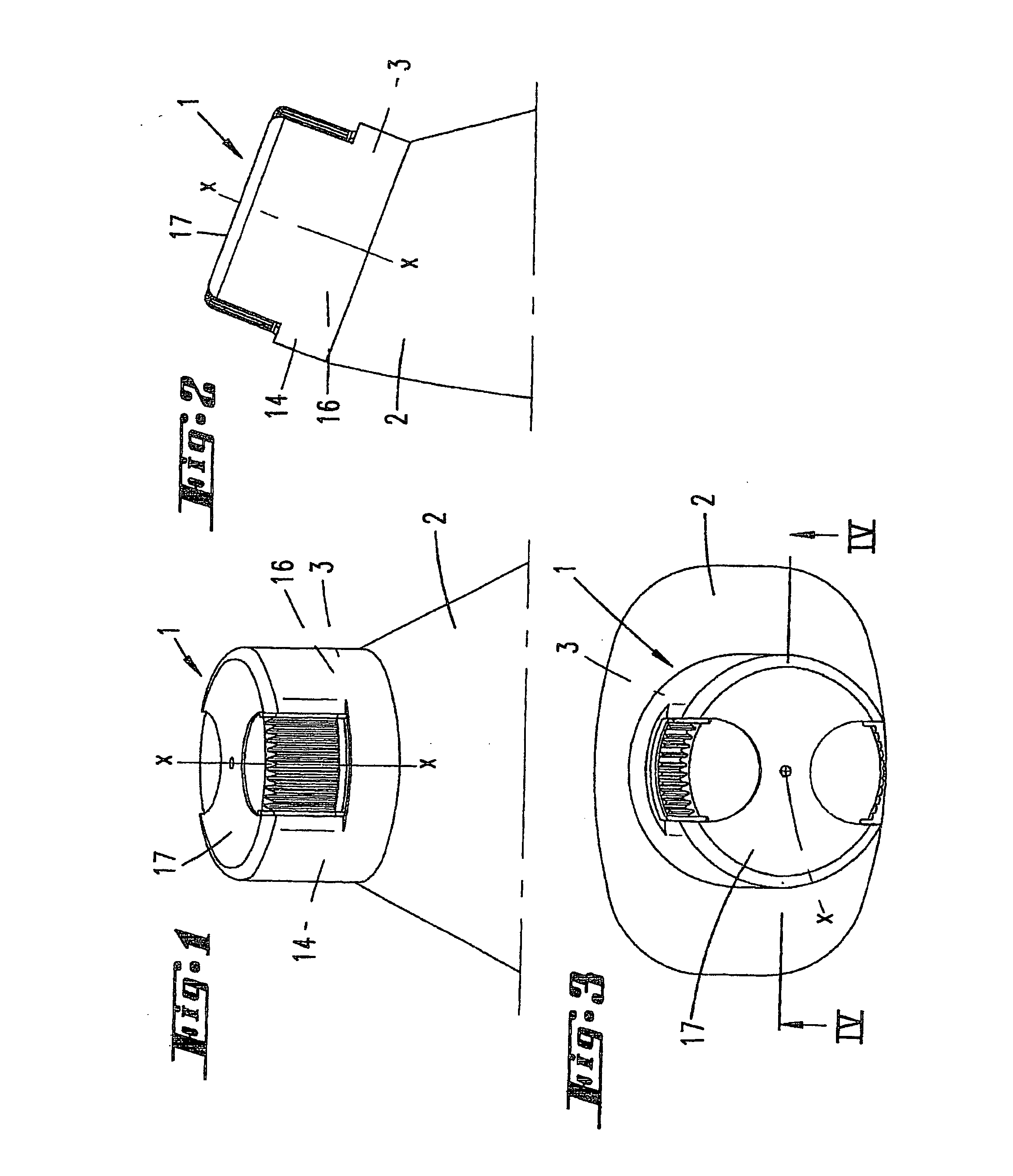
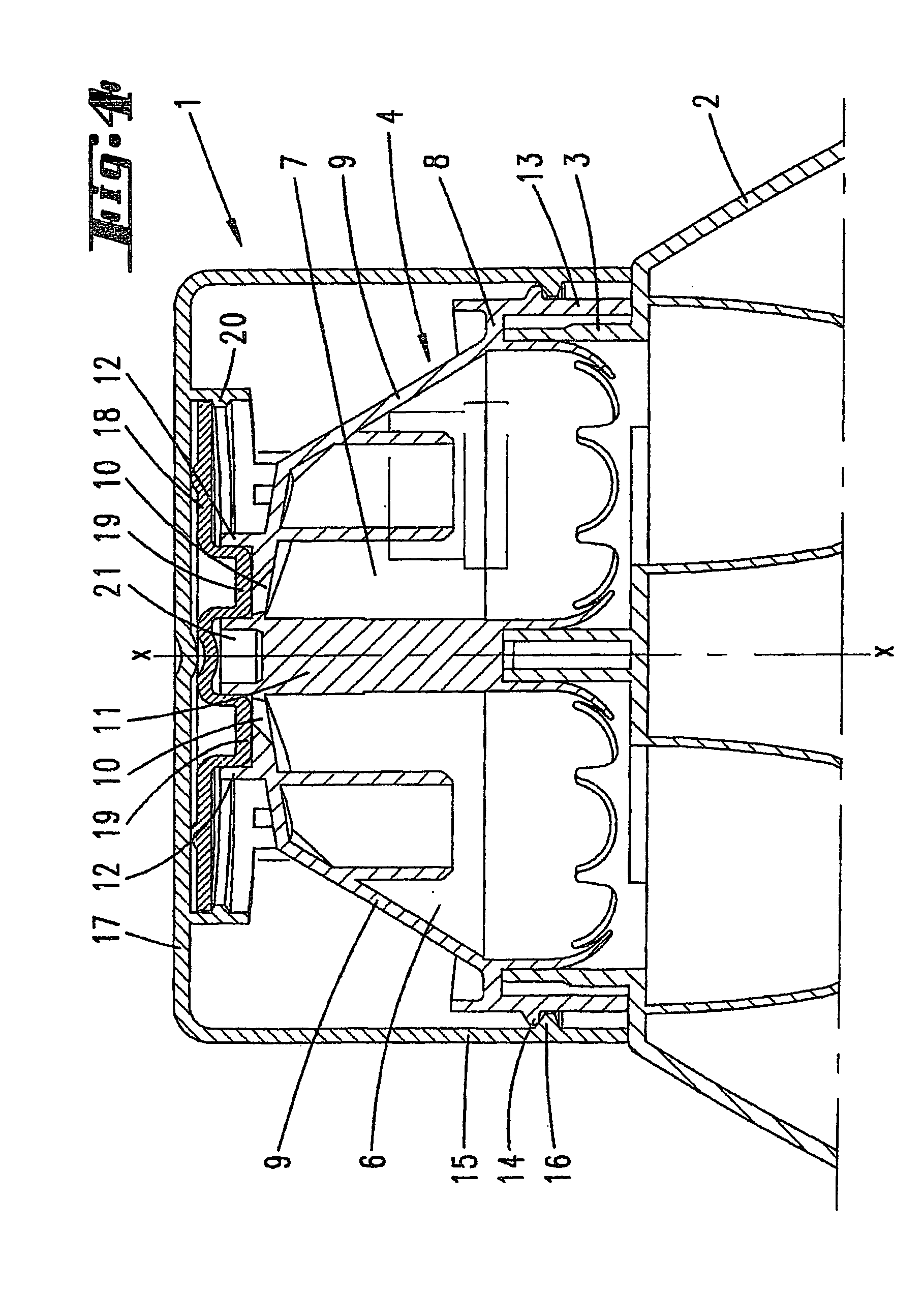
[0032] The holding plate 18, which is illustrated in FIGS. 1 to 8, has a cap-side latching bead 20 engaging over its circumferential edge, this latching bead ensuring on the one hand that the holding plate 18 is held captively on the closure cap 1 and on the other hand that the holding plate 18 can rotate freely on the underside of the cap base 17.

[0033] The two closure stoppers 19 are disposed diametrically opposite, eccentrically with respect to the axis of rotation x, at a spacing from one another which corresponds to the spacing between the two mouthpiece openings 10 of the discharge head 4.

[0034] The diameter of each closure stopper 19 is matched to the internal diameter of the annular walls 12 of the mouthpiece openings 10.

[0035] As seen in the direction of rotation of the holding plate 18, rotary-alignment parts 21 are formed on the underside of the holding plate 18, between the two oppositely-disposed closure stoppers 19. These rotary-alignment parts 21 are formed as circl...

second embodiment

[0038] FIGS. 9 to 11 show the closure cap 1, in which the diameter of the holding plate 18 is reduced compared to the first exemplary embodiment, having approximately half the diameter by comparison with the latter. An inwardly facing latching pin 23 is formed on the cap base 17 to rotatably fix the holding plate 18. This latching pin 23 is preferably formed integrally with the cap base 17, from the same material, and to rotatably fix the holding plate 18 has an annular collar 25 which engages over a central aperture 24 in the holding plate 18.

[0039] On account of the selected formation, the aperture 24 is positioned centrally between the two closure stoppers 19. The way in which the closure stoppers 19 and rotary-alignment parts 21 are disposed and oriented, and also their respective size ratios, correspond to those of the first embodiment.

[0040] To facilitate fitting of the holding plate 18, radially oriented, web-like centering formations 26, which point downward from the cap ba...


PUM


Abstract

The invention relates to a closure cap which is preferably produced according to a plastic injection moulding method and provided with a closure stopper which can be placed on a neck opening which is also preferably made of plastic, said neck opening being that of a bottle container. The closure cap is provided with a bottom and the closure stopper is formed on the inner side of the cap bottom opposite the neck opening. In order to create a functionally secure stopper, said closure stopper is arranged on a plane in a parallel position with regard to the cap bottom such that it can pivot in relation thereto.

Description

CROSS-REFERENCE TO RELATED APPLICATIONS [0001] The present application is a continuation of pending International patent application PCT / EP2004 / 051993 filed on Sep. 1, 2004 which designates the United States and claims priority from German patent application Nos. 10344242.1 filed on Sep. 23, 2003 and 10361613.6 filed on Dec. 30, 2003, the content of which is incorporated herein by reference.FIELD OF THE INVENTION [0002] The invention relates firstly to a closure cap which is produced using the plastics injection molding process. The invention further relates to a combination of a closure cap and a receiving vessel. BACKGROUND OF THE INVENTION [0003] Various embodiments of closure caps of the type in question are known, such as in particular closure caps which, on the inner side of the cap base, have a central closure stopper, formed integrally on the base, for a mouthpiece opening. [0004] Among known closures of the above-mentioned kind, compare for example DE 196 16 000 A1 and SU 1...

Claims


Application Information

Patent Timeline
Patent Type & Authority Applications(United States)
IPC IPC(8): B65D25/08B65D1/04B65D41/04
CPCB65D1/04B65D41/0435B65D2251/04
Inventor SUFFA, UDO
Owner ALPLA WERKE ALWIN LEHNER
Why Eureka
Try Eureka