Electromotor stator coaxially wound around center shaft line in an extending manner and method for manufacturing same

A central axis and coaxial technology, applied in the field of manufacturing motors according to the type of independent claim, can solve problems such as troublesome removal, increased vibration, and inability to ensure the coaxiality of bearings and armatures, so as to save production steps and effectively The effect of orbiting

Active Publication Date: 2014-11-19
ROBERT BOSCH GMBH
View PDF7 Cites 3 Cited by
  • Summary
  • Abstract
  • Description
  • Claims
  • Application Information

AI Technical Summary

Problems solved by technology

[0003] However, such stators have the disadvantage that they have to be removed from the injection mold in a troublesome manner
Furthermore,

Method used


Image

  • Electromotor stator coaxially wound around center shaft line in an extending manner and method for manufacturing same
  • Electromotor stator coaxially wound around center shaft line in an extending manner and method for manufacturing same
  • Electromotor stator coaxially wound around center shaft line in an extending manner and method for manufacturing same

Examples


Embodiment Construction

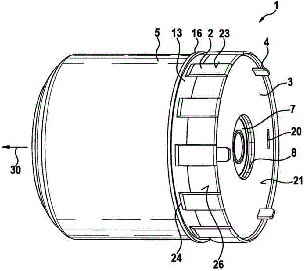
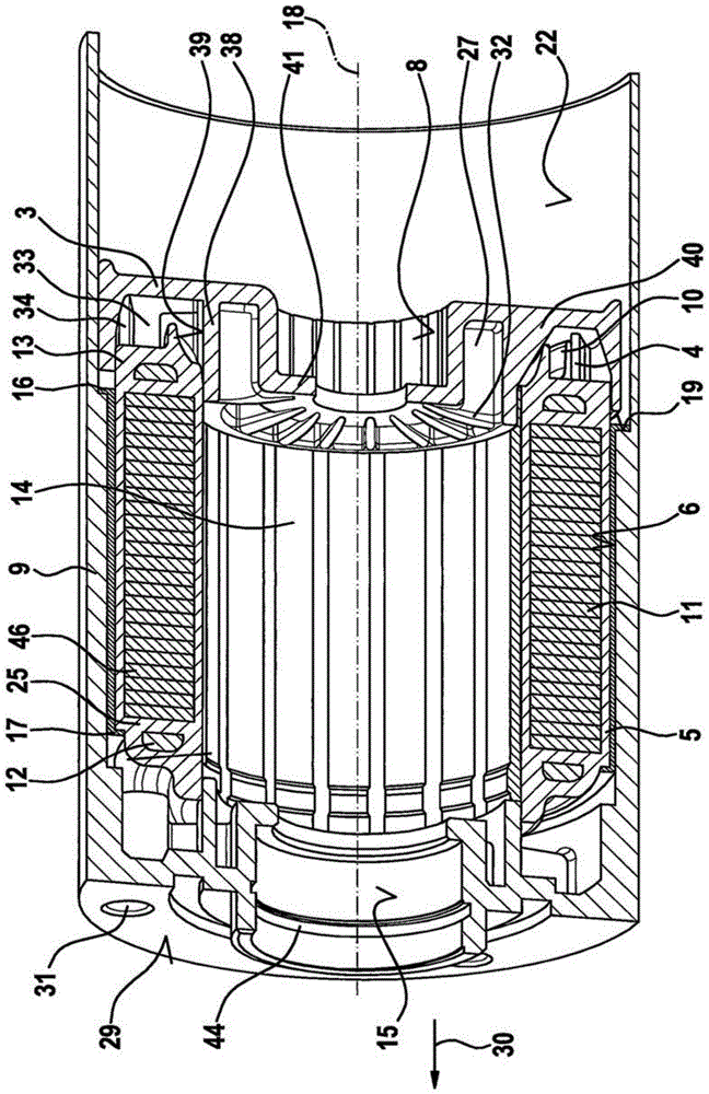
[0024] exist figure 1A stator unit 1 with a bearing carrier cover 3 is shown in . The stator unit 1 comprises a tube 5 made of metal with a stator 11 arranged in the tube 5 and in the figure 2 The section is shown in . The stator unit 1 with the bearing-carrying cover 3 is part of the electric machine. An injection molding 13 is arranged between the stator 11 and the tube 5 . The injection molding encapsulation 13 is formed by means of an injection molding tool. The injection molding tool is engaged on the axial end of the tube 5 . Injection molding tools include nozzles, injection molds and further parts and components necessary for injection molding. It is also conceivable to have additional connections for injection molding tools on the radial side of the tube 5 . The injection molding 6 partially protrudes from the tube 5 at both axial ends. The tube 5 can also have a polymer coating, wherein the polymer coating fits onto the tube radially on the outside.

[0025]...


PUM


Abstract

The invention relates to a stator (11) used for an electromotor. The stator is coaxially wound around a central shaft line (18) in an extending manner. The stator (11) is provided with an electric winding (12) arranged on winding teeth, the electric winding is provided with a wire material continuing part (10) and an electric connector (4) that are applied to the electric contact part (34). The stator (11) is provided with an injection molding encapsulating part (13) which at least partially surrounds the winding (12), the stator (11) is coaxially arranged in a tube (5), the injection molding encapsulating part (13) is arranged in the tube (5), and the invention also relates to a method for manufacturing the electromotor having the stator.

Description

technical field [0001] The invention relates to an electric machine and to a method for producing an electric machine of the type according to the independent claim. Background technique [0002] An electric machine is known from document US 2004 / 0056383 A1, in which the stator is surrounded by an injection-molded encapsulation. The stator segments are assembled prior to injection molding. The injection molding takes place in an injection mold provided for this purpose, into which the components to be injection molded, such as the stator and other components, are inserted. After injection-molding, the injection-molded stator is removed from the injection-molding mold again. The injection-molded stator has injection-molded fixing elements which interact with pin-shaped fixing means in order to fix the stator. [0003] However, such stators have disadvantages such as having to be cumbersomely removed from the injection mould. Furthermore, the manufacturing process cannot e...

Claims


Application Information

Patent Timeline
IPC IPC(8): H02K1/22H02K3/32H02K5/16H02K5/22H02K15/12
CPCH02K5/15H02K1/185H02K3/48H02K5/08H02K15/028H02K2213/12
Inventor F·西蒙Z·兰贝特P·绍洛伊
Owner ROBERT BOSCH GMBH
Why Eureka
Try Eureka