Transceiver element for an active, electronically controlled antenna system

a technology of electronic control and transmitter element, applied in the direction of antennas, multi-antenna systems, antennas, etc., can solve the problems of inability to meaningfully evaluate signals, inability to change frequency bands, and inability to reliably and effectively work with amplitude and phase adjusters, etc., to achieve low losses

Active Publication Date: 2017-03-21
HENSOLDT SENSORS GMBH
View PDF17 Cites 3 Cited by
  • Summary
  • Abstract
  • Description
  • Claims
  • Application Information

AI Technical Summary

Benefits of technology

[0008]Amplitude and phase adjusters are used, first, to compensate the electrical manufacturing tolerances present between the individual transceiver modules and, secondly, to adjust in a predefinable manner the amplitude and phase differences for the transmission and / or reception waves in the case of adjacent transmitter-antenna and / or receiver-antenna elements connected to the transceiver modules. Hence, electrical adjustment and / or spatial pivoting of the transmit / receive radiation pattern of the antenna is possible.
[0013]Exemplary embodiments of the present invention are directed to a transceiver module with which it is possible to achieve reliable and effective signal evaluation over a frequency band which is of any width.
[0019]In another embodiment of the invention, the number N of connections A1, . . . , N and B1, . . . , N of the first and second single-pole multiple-throw switches is 2, 3, 4, 5, 6 or 7. Expediently, the number N of connections A1, . . . , N or B1, . . . , N of the first or second single-pole multiple-throw switches is 4, that is to say N=4, and so a single-pole four-throw (SP4T) switch known from the prior art can be used. SP4T switches known from the prior art have low losses.

Problems solved by technology

One problem of known antenna systems is that the amplitude and phase adjusters can work reliably and effectively only within a predefined restricted frequency band.
Outside of this frequency band to which the amplitude and phase adjuster of a transceiver module is tuned, meaningful signal evaluation is not possible.
In the case of an antenna system with fixedly installed transceiver modules, it is not possible to change the frequency band.

Method used


Image

  • Transceiver element for an active, electronically controlled antenna system
  • Transceiver element for an active, electronically controlled antenna system
  • Transceiver element for an active, electronically controlled antenna system

Examples


Embodiment Construction

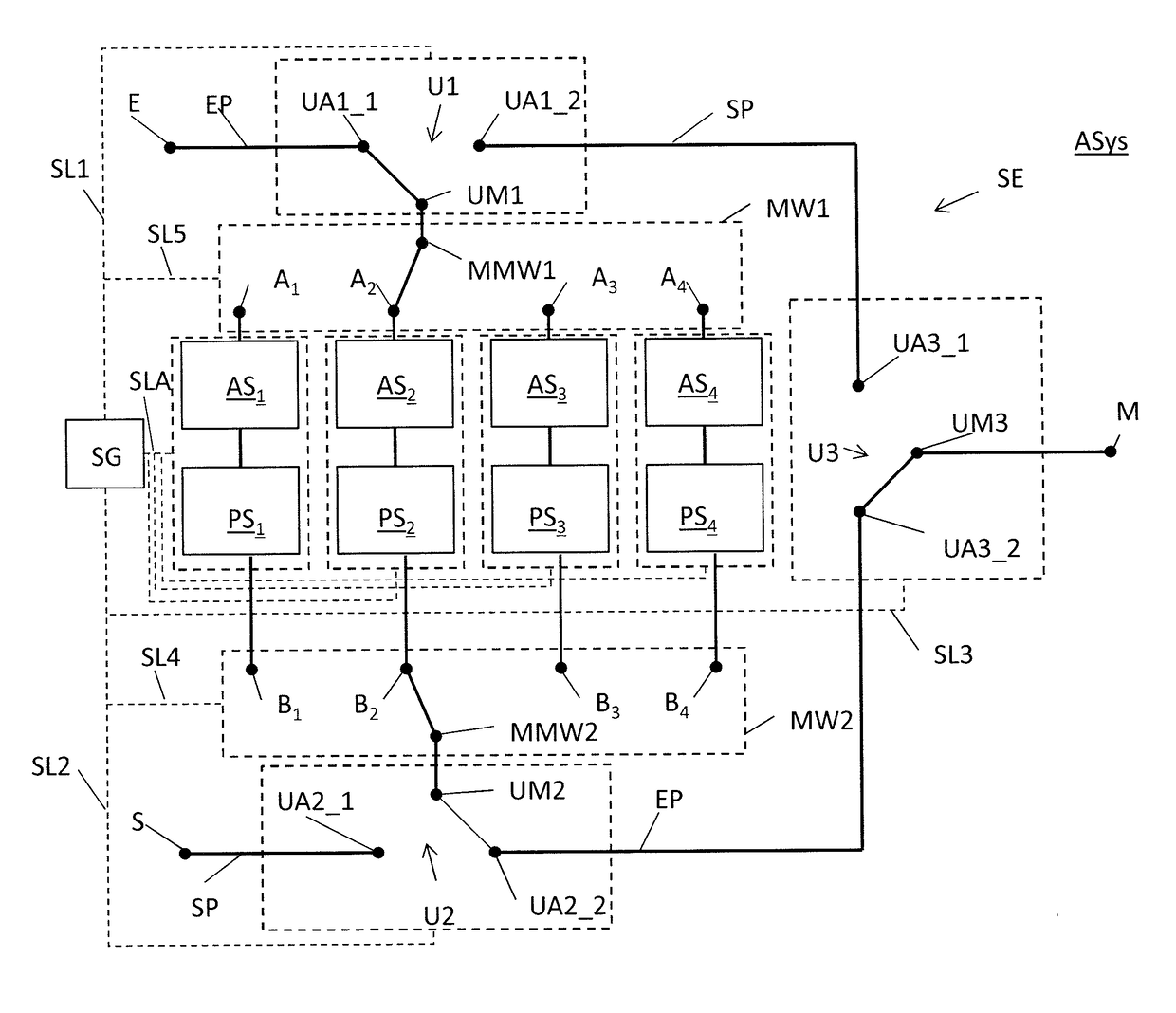
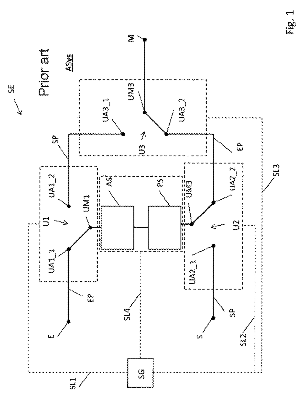
[0028]FIG. 1 shows a schematic design of a transceiver module SE according to the prior art. The transceiver module SE of the antenna system ASys has an input E for a receiver (not shown) and an output S for a transmitter (not shown). Furthermore, a connection M is present which leads to the down or up conversion mixer (not shown)

[0029]The transceiver module SE has three single-pole changeover switches U1, U2, U3. The single-pole changeover switches U1, U2, U3 make it possible to change over between a transmit path SP and a receive path EP in the transceiver module SE. Each single-pole changeover switch U1, U2, U3 has in each case a common central connection UM1, UM2, UM3. Furthermore, each single-pole changeover switch U1, U2, U3 has two connections UA1_1, UA1_2; UA2_1, UA2_2; UA3_1, UA3_2 by means of which the input E can be connected to the connection M via the receive path EP or the input S can be connected to the connection M via the transmit path SP.

[0030]Furthermore, a contro...


PUM


Abstract

A transceiver element for an active, electronically controlled antenna system includes a transmit path, a receive path and single-pole change-over switches having a common central connection and two connections for switching between the transmit path and the receive path. An amplitude controller and a phase adjuster are arranged between the common center connections of a first and second single-pole change-over switch. Single-pole multiple toggle switches having a common central connection and a number N of connections are present. The common central connection of the first and second single-pole change-over switch is connected to the common central connection of a first and a second single-pole multiple toggle switch respectively, and an amplitude controller and a phase adjuster are connected between each connection of the number N of connections of the first multiple toggle switch and the second multiple toggle switch.

Description

BACKGROUND AND SUMMARY OF THE INVENTION[0001]Exemplary embodiments of the invention relate to a transceiver element for an active, electronically controlled antenna system.[0002]Active, electronically controlled antenna systems consist, in principle, of the three subsystems:[0003]A. RF splitter and combiner system (also referred to as RF supply system),[0004]B. active transmitter modules, receiver modules or combined active transmit / receive modules, also referred to as T / R modules, arranged between the antenna-side outputs of the RF supply system and the antenna elements, and[0005]C. the antenna elements which, together, cover a common antenna aperture.[0006]A typical antenna system such as this contains a multiplicity of transmitter-antenna and / or receiver-antenna elements arranged linearly or in a matrix, which are only at a short distance apart from one another, usually a spacing of approximately λ / 2, wherein λ is the transceiver wavelength. A transceiver module is directly coupl...

Claims


Application Information

Patent Timeline
Patent Type & Authority Patents(United States)
IPC IPC(8): H04B1/44H04Q3/28H01Q3/34H04B7/12H04B1/00H01Q3/28H01Q3/38H01Q21/00
CPCH04B1/006H04B7/12H04B1/44H01Q3/28H01Q3/34H01Q3/38H01Q21/0025
Inventor CHARTIER, SEBASTIEN
Owner HENSOLDT SENSORS GMBH
Why Eureka
Try Eureka