Pressure-boosted fuel injection device comprising an internal control line

a fuel injection device and internal control line technology, applied in fuel injection apparatus, feeding system, spraying apparatus, etc., can solve the problems of high material stress at the bore intersection and require costly machining steps, and achieve the effect of improving the high-pressure tightness of the fuel injector

a fuel injection device and internal control line technology, applied in fuel injection apparatus, feeding system, spraying apparatus, etc., can solve the problems of high material stress at the bore intersection and require costly machining steps, and achieve the effect of improving the high-pressure tightness of the fuel injector

US7513440B2Inactive Publication Date: 2009-04-07ROBERT BOSCH GMBH

Image

  • Pressure-boosted fuel injection device comprising an internal control line
  • Pressure-boosted fuel injection device comprising an internal control line
  • Pressure-boosted fuel injection device comprising an internal control line

Examples


Embodiment Construction

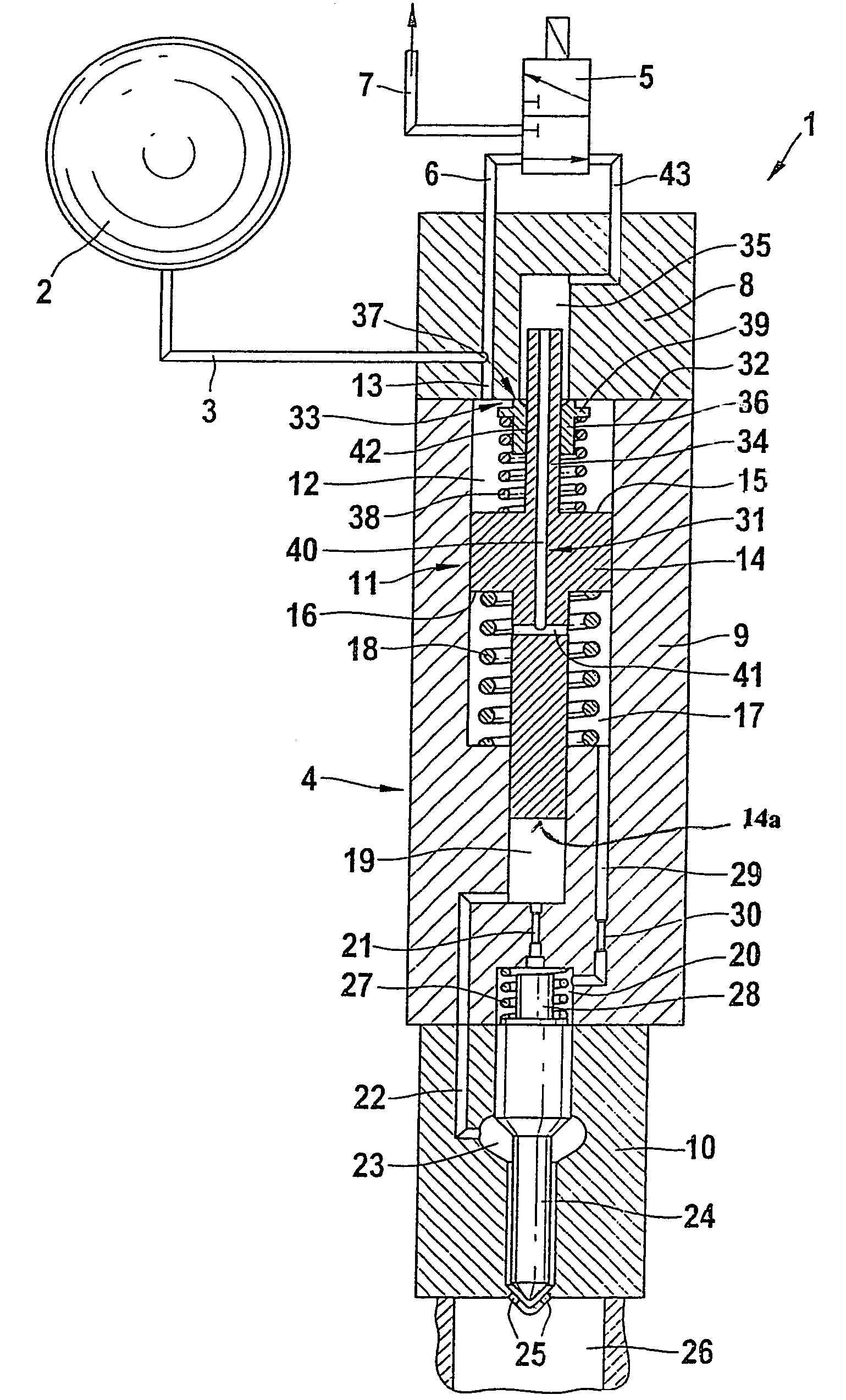
[0018]FIG. 1 shows an embodiment variant of a fuel injector with pressure booster whose piston has a piston extension with a section of the central control line passing through it.

[0019]According to the first exemplary embodiment of the concept underlying the invention shown in FIG. 1, a high-pressure reservoir 2 (common rail) acts on a fuel injection device 1 with highly pressurized fuel. The highly pressurized fuel contained in the high-pressure reservoir 2 flows to an injector body 4 of the fuel injection device 1 via a high-pressure line 3. The high-pressure line 3 feeds into a first housing part 8 of the fuel injection device 1. From the first housing part 8, an inlet 6 extends to an on-off valve 5. On the one hand, the on-off valve 5 has a low-pressure side return 7 branching from it, which feeds into a fuel reservoir not shown in FIG. 1, and on the other hand, the valve has an overflow line 43, which communicates with a recess 35 inside the first housing part 8.

[0020]The inje...


PUM


Abstract

The invention relates to a fuel injection device with a multi-part injector body containing a pressure booster that can be actuated by means of a differential pressure chamber, and includes a pressure booster piston that seals a working chamber off from the differential pressure chamber. An on-off valve disposed above the injector body can actuate the fuel injection device. A pressure change in the differential pressure chamber occurs via a central control line that extends through the pressure booster piston of the pressure booster.

Description

CROSS-REFERENCE TO RELATED APPLICATIONS[0001]This application is a 35 USC 371 application of PCT / DE 03 / 03314 filed on Oct. 7, 2003.BACKGROUND OF THE INVENTION[0002]1. Field of the Invention[0003]Both pressure-controlled and stroke-controlled injection systems can be used to deliver fuel into combustion chambers of autoignition internal combustion engines. Injection systems with high-pressure reservoirs have the advantage that the injection pressure can be adapted to the load and speed of the engine. A high injection pressure is required in order to reduce emissions produced and to achieve a high specific output of the engine. Since the pressure level that high-pressure fuel pumps can achieve in the high-pressure reservoir is limited for strength reasons, a pressure booster at the fuel injector can be used to boost pressure further in fuel injection devices with a high-pressure reservoir.[0004]2. Prior Art[0005]DE 199 10 907 A1 has disclosed a fuel injection device that has a pressur...

Claims


Application Information

Patent Timeline
07 Apr 2009
Publication
US7513440B2
IPC
F02M47/02; F02M57/02; F02M61/20; F02M63/00
CPC
F02M47/025; F02M47/027; F02M57/025; F02M57/026; F02M61/205; F02M63/0005; F02M63/0007; F02M63/0015
Inventors
MAGEL, HANS-CHRISTOPH