Electroplating contact ring with radially offset contact fingers

a contact ring and radial offset technology, applied in the direction of contacting devices, electrolysis components, electrolysis processes, etc., can solve the problems of poor plating uniformity, reducing device yield, and difficulty in providing electroplating apparatus, and achieve good electroplating results

Active Publication Date: 2017-09-28
APPLIED MATERIALS INC
View PDF3 Cites 3 Cited by
  • Summary
  • Abstract
  • Description
  • Claims
  • Application Information

AI Technical Summary

Benefits of technology

[0005]A contact ring has redundant contact fingers, i.e., more contact fingers than needed for contacting a very narrow edge exclusion zone. The contact fingers may have slightly different lengths so that they extend to different radial positions. By providing redundant contact fingers, and by slightly varying the lengths of the contact fingers, a sufficient number of contact fingers make contact with the electrically conductive surface in the edge exclusion zone to provide good electroplating results. Although some contact fingers will generally miss the edge exclusion zone, electroplating is not affected. The contact ring compensates for manufacturing tolerances of an exposed seed layer region, and the manufacturing tolerance of the contact ring contact itself.

Problems solved by technology

If the contact fingers only touch the exposed seed layer on portions of the circumference, then poor electrical contact will cause poor plating uniformity reducing device yield.
It is of course very difficult to provide an electroplating apparatus where all of the contact fingers can consistently contact a 0.1 mm edge exclusion zone.
These factors present engineering challenges in designing electroplating apparatus.

Method used


Image

  • Electroplating contact ring with radially offset contact fingers
  • Electroplating contact ring with radially offset contact fingers
  • Electroplating contact ring with radially offset contact fingers

Examples


Embodiment Construction

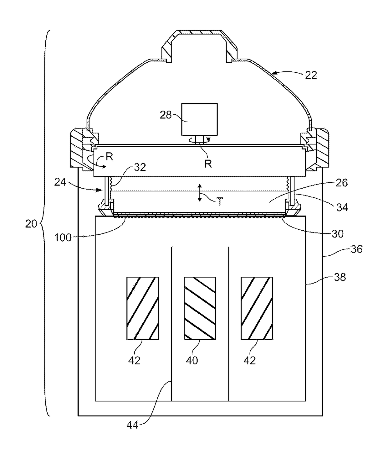
[0013]As shown in FIG. 1, and electroplating processor 20 has a head 22 including a rotor 24. A motor 28 in the head 22 rotates the rotor 24, as indicated by the arrow R in FIG. 1. An annular contact ring 30 on or attachable to the rotor 24 makes electrical contact with a wafer 100 held into or onto the rotor 24. The rotor 24 may include a backing plate 26, and ring actuators 34 for moving the contact ring 30 vertically (in the direction T in FIG. 1 between a wafer load / unload position and a processing position. The head 22 may include bellows 32 to allow for vertical or axial movement of the contact ring while sealing internal head components from process liquids and vapors.

[0014]Referring still to FIG. 1, the head 22 is engaged onto a frame 36. A vessel or bowl 38 within the frame 36 holds electrolyte. The head is movable to position a wafer 100 held in the rotor 24 into contact with electrolyte in the vessel 38. One or more electrodes are positioned in the vessel. The example sho...


PUM

PropertyMeasurementUnit
lengthaaaaaaaaaa
lengthaaaaaaaaaa
thickaaaaaaaaaa

Abstract

A contact ring for an electroprocessor has redundant contact fingers, i.e., more contact fingers than needed for contacting a very narrow edge exclusion zone on a substrate such as a semiconductor wafer. The contact fingers have slightly different lengths so that they extend to different radial positions. By providing redundant contact fingers, and by slightly varying the lengths of the contact fingers, a sufficient number of contact fingers make contact with the electrically conductive surface in the edge exclusion zone to provide good electroplating results.

Description

PRIORITY CLAIM[0001]This application claims priority to U.S. Patent Application No. 62 / 313,052, filed Mar. 24, 2016, and now pending.BACKGROUND OF THE INVENTION[0002]Electroplating and electropolishing of microelectronic workpieces, such as silicon wafers, typically involves immersing an electrically conductive surface of the wafer into a bath of liquid electrolyte. Electric current is passed through the electrolyte causing metal ions in the electrolyte to plate out onto the surface of the wafer, forming a plated layer or film. The electrical connection to the electrically conductive surface of the wafer may only be made in the so-called edge exclusion zone, as specified by industry standards. The edge exclusion zone is narrow, typically about 3 mm under current industry standards, and 2 mm or less in proposed future industry standards. In the past, contact rings having multiple spring-like contact fingers have been successfully used to provide the electrical connection to the wafer...

Claims


Application Information

Patent Timeline
Patent Type & Authority Applications(United States)
IPC IPC(8): C25D17/00H01L21/288C25D5/02C25D5/56H01R4/48C25D7/12
CPCC25D17/005H01R4/48H01L21/2885C25D5/022C25D5/56C25D7/123C25D17/001H01R39/18H01R39/64H01L21/68721H01L21/68735
Inventor WILSON, GREGORY J.
Owner APPLIED MATERIALS INC
Why Eureka
Try Eureka