Microvolume flowcell apparatus

a flowcell and micro-volume technology, applied in the direction of analytical using chemical indicators, laboratory glassware, instruments, etc., can solve the problems of uniform optical characteristics, difficult cleaning, and large sample volum

Inactive Publication Date: 2006-08-31
LEVINE LEANNA M
View PDF6 Cites 18 Cited by
  • Summary
  • Abstract
  • Description
  • Claims
  • Application Information

AI Technical Summary

Problems solved by technology

Such flowcells require a relatively large sample volume, on the order of 100 microliters or greater and are fragile and difficult to clean.
In addition, the fabrication process generally results in non-uniform optical characteristics producing variations in transmitted or reflected light from unit to unit.

Method used


Image

  • Microvolume flowcell apparatus
  • Microvolume flowcell apparatus
  • Microvolume flowcell apparatus

Examples


Embodiment Construction

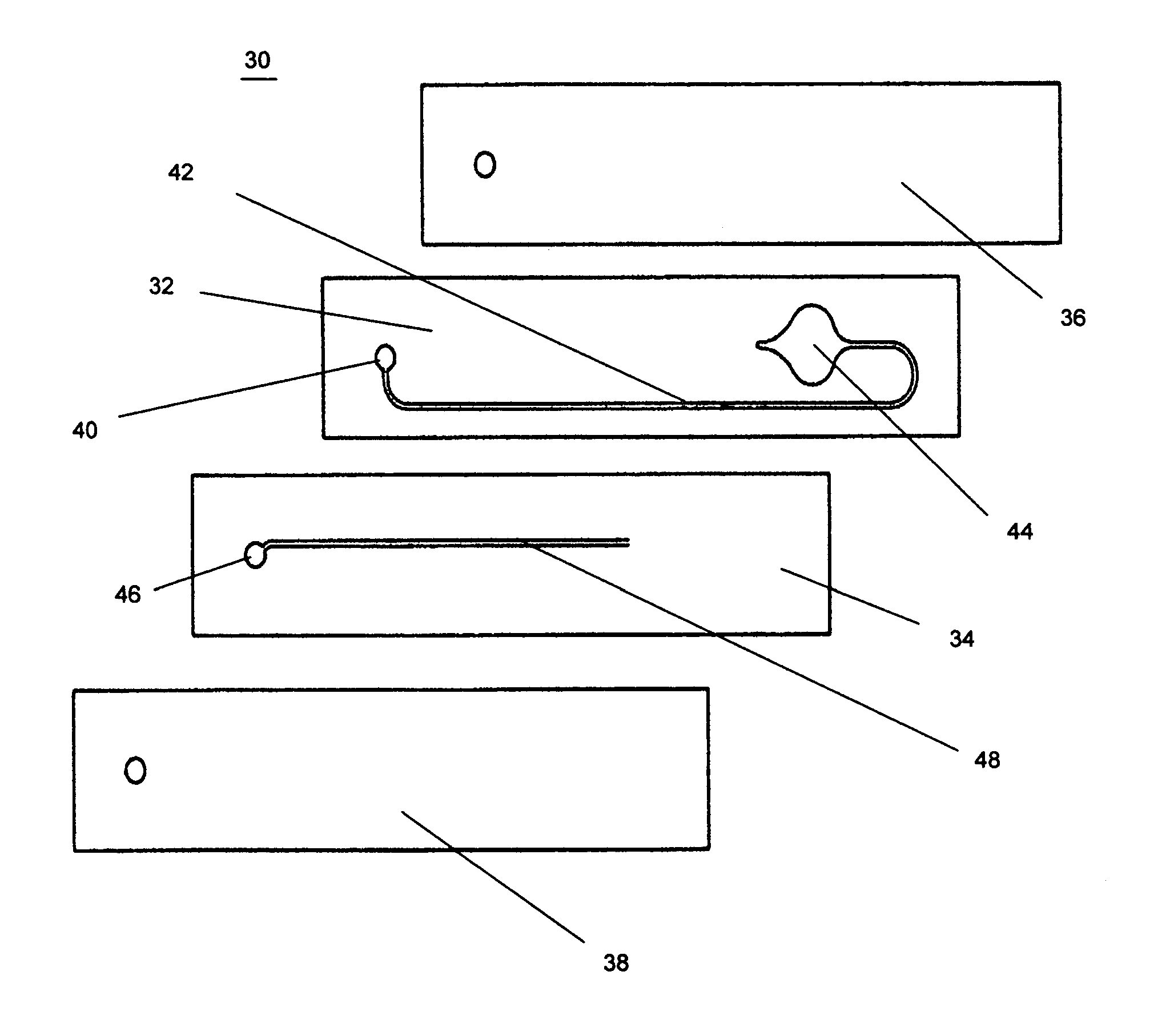
[0017] The apparatus of the invention comprises a disposable microflowcell and support fixture to enable real-time monitoring of chemical and biological samples. The invention is adapted to fit into a conventional cuvette holder found in spectrophotometer or fluorimeter type instruments.

[0018] A typical sample to be analyzed by such instruments requires that the cuvette or sample holder contain a minimum sample volume of at least 70 microliters. The microflowcell of the invention, however, can contain chemical or biological samples having sample volumes from about 0.1 to about 30.0 microliters.

[0019] The design of the microflowcell allows real-time monitoring of changes in an analyte in the sample stream and permits the same sample volume to be monitored under a variety of sample concentrations. The apparatus of the invention can fit into a standard 1 cm×1 cm cuvette holder.

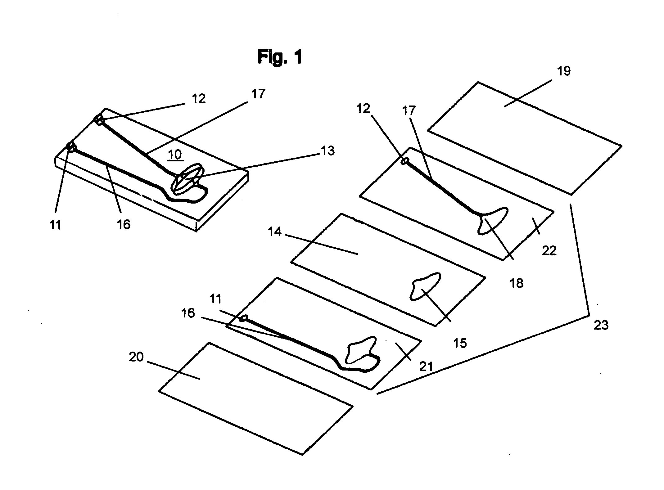
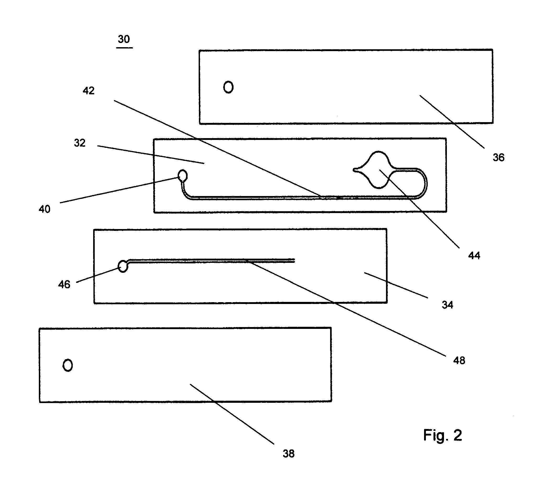
[0020] With reference to FIG. 1, a flowcell 10 of the invention comprises a laminated layer assembly having...


PUM


Abstract

A compact microflowcell apparatus having a disposable flowcell unit that can be fabricated with uniform optical characteristics and an associated support fixture adapted to be placed in the sample compartment of a standard fluorimeter or spectrophotometer to accommodate different light path configurations in such instruments.

Description

CROSS-REFERENCE TO RELATED APPLICATIONS [0001] The present application claims the benefit of priority of Provisional Patent Application Ser. No. 60 / 656,803 filed Feb. 25, 2005 for Leanna M. Levine, the entire content of which is incorporated herein by reference.FIELD OF THE INVENTION [0002] The invention relates to a compact microflowcell apparatus for use in spectrographic and fluorimetric measuring equipment. BACKGROUND OF THE INVENTION [0003] A flowcell is generally defined as a device carrying a solution stream that is placed in a path between a light source and light detection system to measure the optical characteristics of the solution stream. [0004] Flowcells are commonly used in devices such as a spectrophotometer, colorimeter, or fluorimeter to measure the light transmissivity, absorbance, and reflectivity characteristics of fluids, solutions, or gases; either in stasis or in dynamic flow. [0005] In practice, the flowcell is fixedly mounted in a suitable holder that is pla...

Claims


Application Information

Patent Timeline
Patent Type & Authority Applications(United States)
IPC IPC(8): B01L3/00
CPCB01L3/502715B01L2300/0654B01L2300/0816B01L2300/0887G01N21/05G01N2021/0321G01N2201/066G01N2021/0346
Inventor LEVINE, LEANNA M.
Owner LEVINE LEANNA M
Why Eureka
Try Eureka