Self-Propelled Agricultural Harvester

a harvester and self-propelled technology, applied in the field of self-propelled harvesters, can solve the problems of affecting the driving behavior of the harvester, affecting the work efficiency of the harvester, so as to improve the driving behavior, improve the safety of traffic, and reduce the weight of the harvesting devi

Inactive Publication Date: 2006-09-07
MASCHFAB BERNARD KRONE GMBH
View PDF10 Cites 9 Cited by
  • Summary
  • Abstract
  • Description
  • Claims
  • Application Information

AI Technical Summary

Benefits of technology

[0016] A further great advantage of the present invention, in particular for improving the traffic safety, resides in the compact dimensions and in the low weight of the harvesting device. These features improve the driving behavior because of the low center of gravity and a short distance to the front axle of the harvester in particular when driving fast on roads.
[0017] In further embodiments, a harvesting device having more than three parts is also conceivable; upon pivoting into the transport position; a package with four or more layers of harvesting device parts is provided by employing the features according to the invention.
[0018] With the configuration of the harvesting device in accordance with the present invention and in particular by means of the inventive arrangement of the pivot axes of the lateral parts, it is possible to operate the harvester with different working widths without having to change the harvesting device by pivoting one or both lateral parts of the harvesting device into a vertical inoperative position. By means of these different operating positions, the harvester operator is provided with entirely new working possibilities. For example, it is possible to employ only the center part of the harvesting device to harvest an area at the boundary of a field; subsequently, this harvested area can be used to completely unfold the harvesting device on the field without losing any of the crop. In particular in the case of harvesting devices with great working width, a complete unfolding outside of the field is often not possible; for this reason, loss of crop by driving into the field and unfolding within the crop to be harvested had to be accepted in the past.
[0019] In an especially advantageous embodiment of the harvesting device of a harvester according to the invention, the working width of the center part of the harvesting device, when the lateral parts are in their inoperative position, is matched in such a way to a standard row spacing of the crop such that safe harvesting of a number of rows is ensured so that additional rows of crop to be harvested are neither damaged nor flattened by driving across by parts of the harvesting device or by the harvester itself.
[0020] Accordingly, by means of the especially advantageous features of the invention a harvester is provided that comprises a very flexibly employable harvesting device with an enlarged working width that, when in the transport position, does not obstruct the field of view of the driver and increases traffic safety for driving the harvester on roads.

Problems solved by technology

The demand for even greater working widths is however limited in this configuration by the legally permissible transport height; moreover, the obstruction of the field of view caused by the halves of the harvesting device that are vertically oriented in the transport position is reduced to a minium by the intelligent arrangement of the pivot axes but is not completely avoidable.
Further known solutions in which the harvesting devices of the harvester are of a multi-part configuration and can be pivoted and / or swivelled about more than two axes enable possibly a greater working width, but all cause an obstruction of the field of view of the driver of the harvester.
A particular disadvantage of such devices is however also their high constructive expenditure and the great weight connected therewith, the difficult handling, the negative effect on the center of gravity of the harvester, and, last but not least, the high manufacturing costs.

Method used


Image

  • Self-Propelled Agricultural Harvester
  • Self-Propelled Agricultural Harvester
  • Self-Propelled Agricultural Harvester

Examples


Embodiment Construction

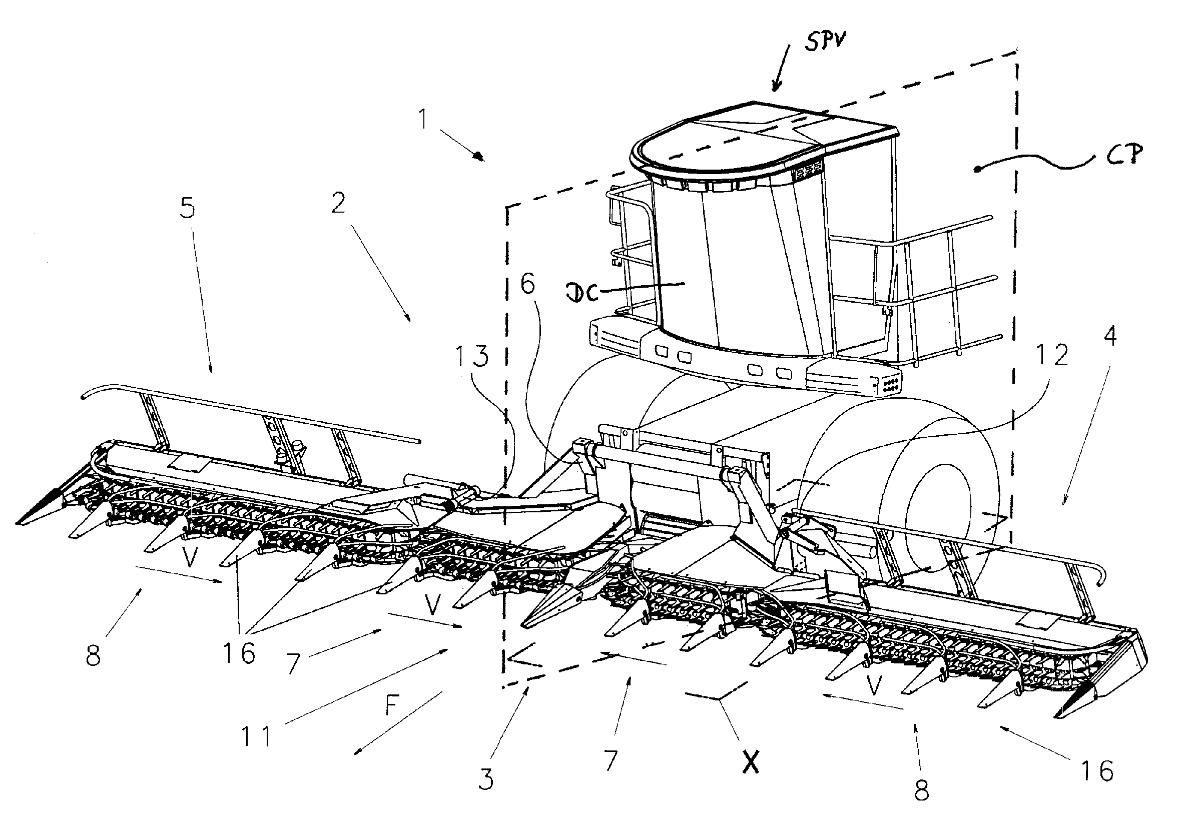
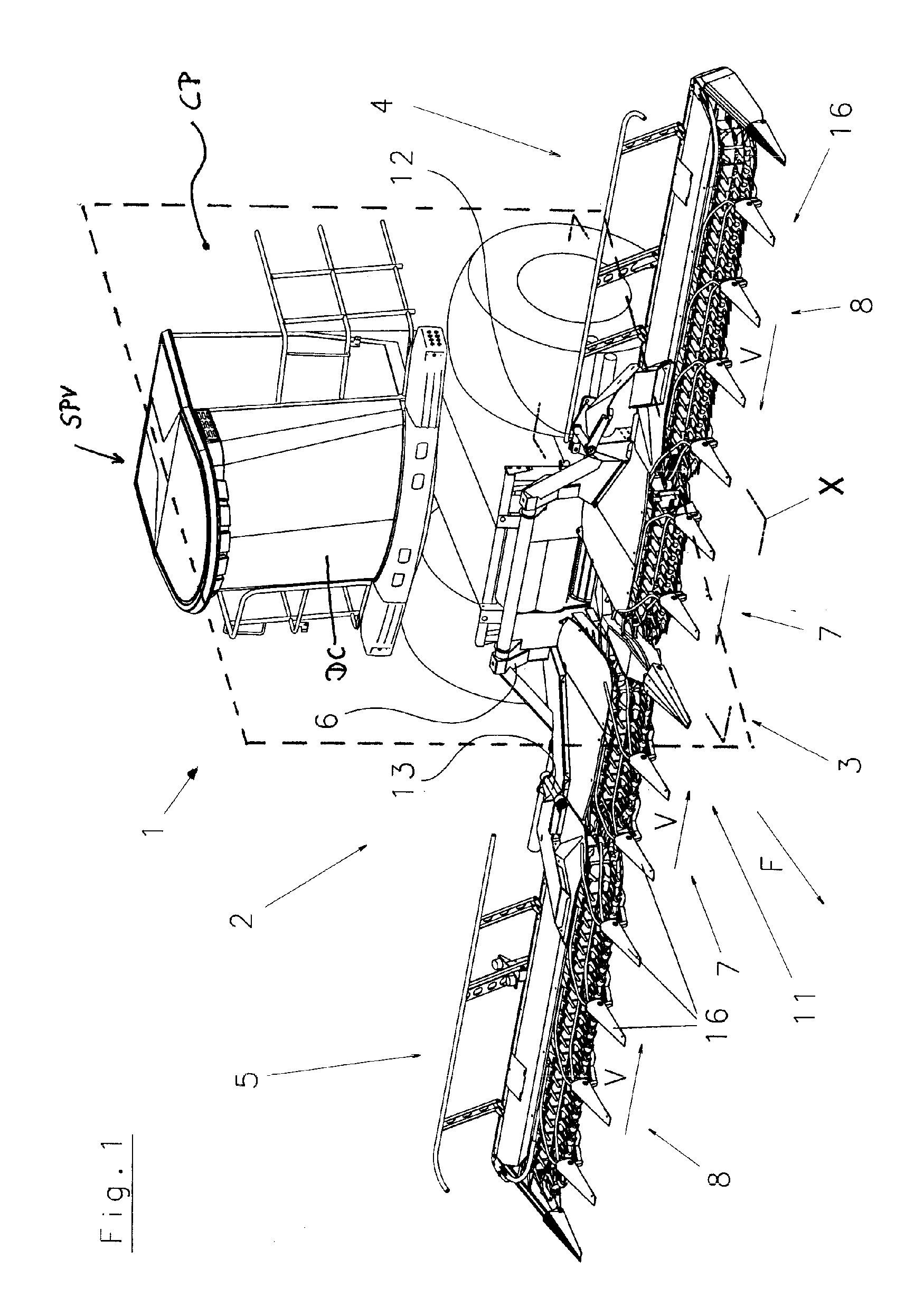
[0024] An embodiment of a self-propelled agricultural harvester 1 in the form of a field chopper with a harvesting device 2 that is used particularly as a front end attachment for row-independent harvesting of stalky crop such as corn or the like is illustrated in detail in FIG. 1. The harvesting device 2 is mounted preferably to the front end of a self-propelled working vehicle SPV (of which only two front wheels and the driver's cab DC are schematically shown) and is comprised preferably, as illustrated, of three parts 3, 4, 5. The central part 3 is connected by means of a base frame 6 fixedly to the harvester. The lateral parts (swivel parts) 4, 5 are pivotably connected to the outward edges of the central part 3 by a pivot axle 12, 13, respectively, defining a pivot axis. In the working position of the harvesting device 2 illustrated in FIG. 1, the lateral parts (swivel parts) 4, 5 are supported on the central part 3 in a way not described in detail and, if needed, are locked th...


PUM


Abstract

A harvester has a harvesting device arranged in a traveling and working direction of the harvester in front of a driver's cab. The harvesting device has first, second, and third parts and extends with its length in a direction transverse to the traveling and working direction. At least the first and second parts are swivel parts that are pivotable about approximately 180 degrees about a pivot axis, respectively. The pivot axis extends approximately in the traveling and working direction, such that the swivel parts are transferable from a working position in which the swivel parts extend transversely to the traveling and working direction into a transport position. In the transport position legally permissible dimensions for traveling on roads are observed. A longitudinal extension of the swivel parts transverse to the traveling and working direction matches at least approximately a maximum legally permissible transport width.

Description

BACKGROUND OF THE INVENTION [0001] The invention relates to a self-propelled agricultural harvester comprising a harvesting device in the form of a mowing and conveying device, a pick-up device or the like that is arranged preferably in the front area in the traveling and / or working direction in front of a driver's cab and is comprised of at least three parts. The harvesting device extends in its longest extension transversely to the traveling and working direction of the harvester. The harvesting device is designed such that by an approximately 180 degree pivot movement of at least two parts of the harvesting device about pivot axes that extend at least approximately in the traveling and working direction these parts can be transferred from an operating position, in which they extend transversely to the traveling and working direction, into a transport position so that the legally permissible dimensions, particularly the transport width, for a harvester traveling on roads are obser...

Claims


Application Information

Patent Timeline
Patent Type & Authority Applications(United States)
IPC IPC(8): A01B73/00
CPCA01D41/144
Inventor KRONE, BERNARDHORSTMANN, JOSEFOVERMEYER, BERNWARDESTER, MARKUS
Owner MASCHFAB BERNARD KRONE GMBH
Why Eureka
Try Eureka