Oven

a technology for ovens and ovens, applied in the field of ovens, can solve the problems of inability to efficiently and rapidly cool the door, the ambient air does not flow uniformly over the entire surface of the door, and the door cannot be efficiently and rapidly cooled, so as to achieve effective and rapid cooling of the cooking chamber door

Active Publication Date: 2006-09-07
SAMSUNG ELECTRONICS CO LTD
View PDF4 Cites 24 Cited by
  • Summary
  • Abstract
  • Description
  • Claims
  • Application Information

AI Technical Summary

Benefits of technology

[0010] Accordingly, an aspect of the invention is to provide an oven capable of effectively and rapidly cooling a cooking chamber door by causing a sufficient quantity of cooling air to flow through the cooking chamber door and preventing the cooling air from being mixed with hot air discharged from the oven.

Problems solved by technology

However, since the cooling fan, in the conventional oven, forces ambient air from an upper side to a lower side of the door through a nozzle, ambient air does not flow uniformly over the entire surface of the door.
Thus, the door cannot be efficiently and rapidly cooled.
Moreover, since the conventional oven does not have a structure for separating hot air generated while cooking food in the cooking chamber from cooling air and discharging the hot air, it is difficult to devise a structure capable of reducing the door temperature.

Method used


Image

  • Oven
  • Oven
  • Oven

Examples


Embodiment Construction

[0028] Reference will now be made in detail to the embodiments of the present invention, examples of which are illustrated in the accompanying drawings, wherein like reference numerals refer to the like elements throughout. The embodiments are described below to explain the present invention by referring to the figures.

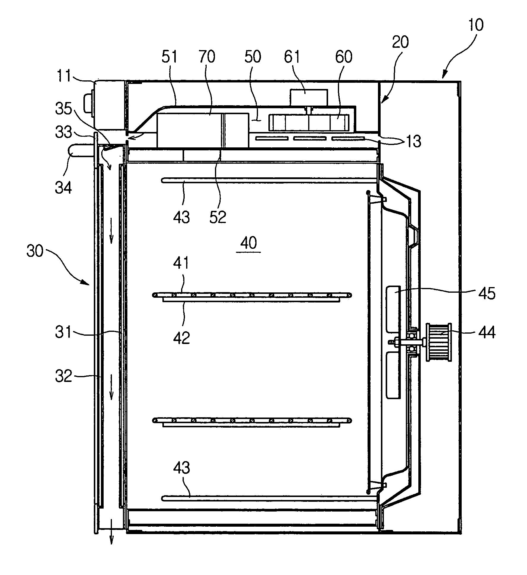
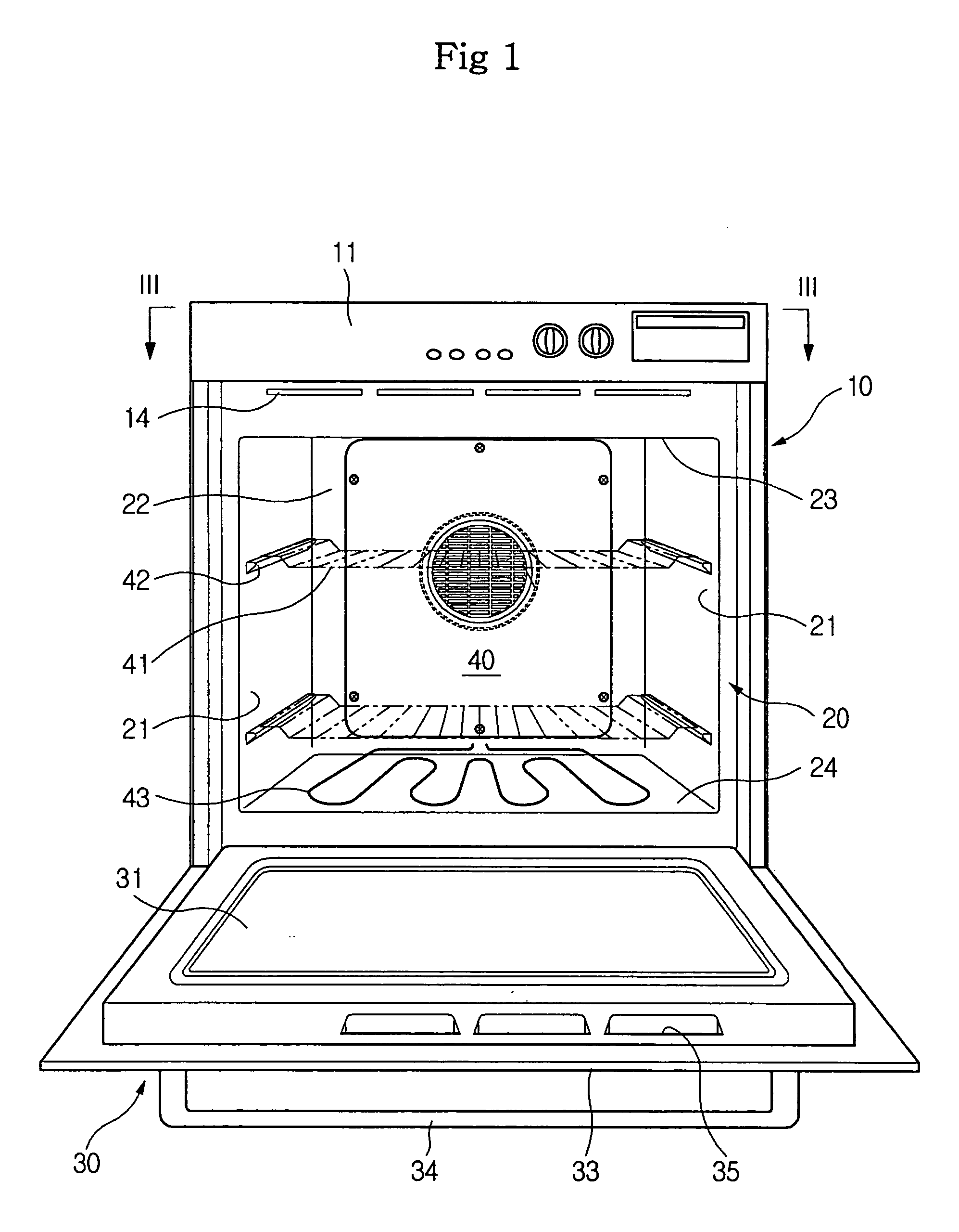
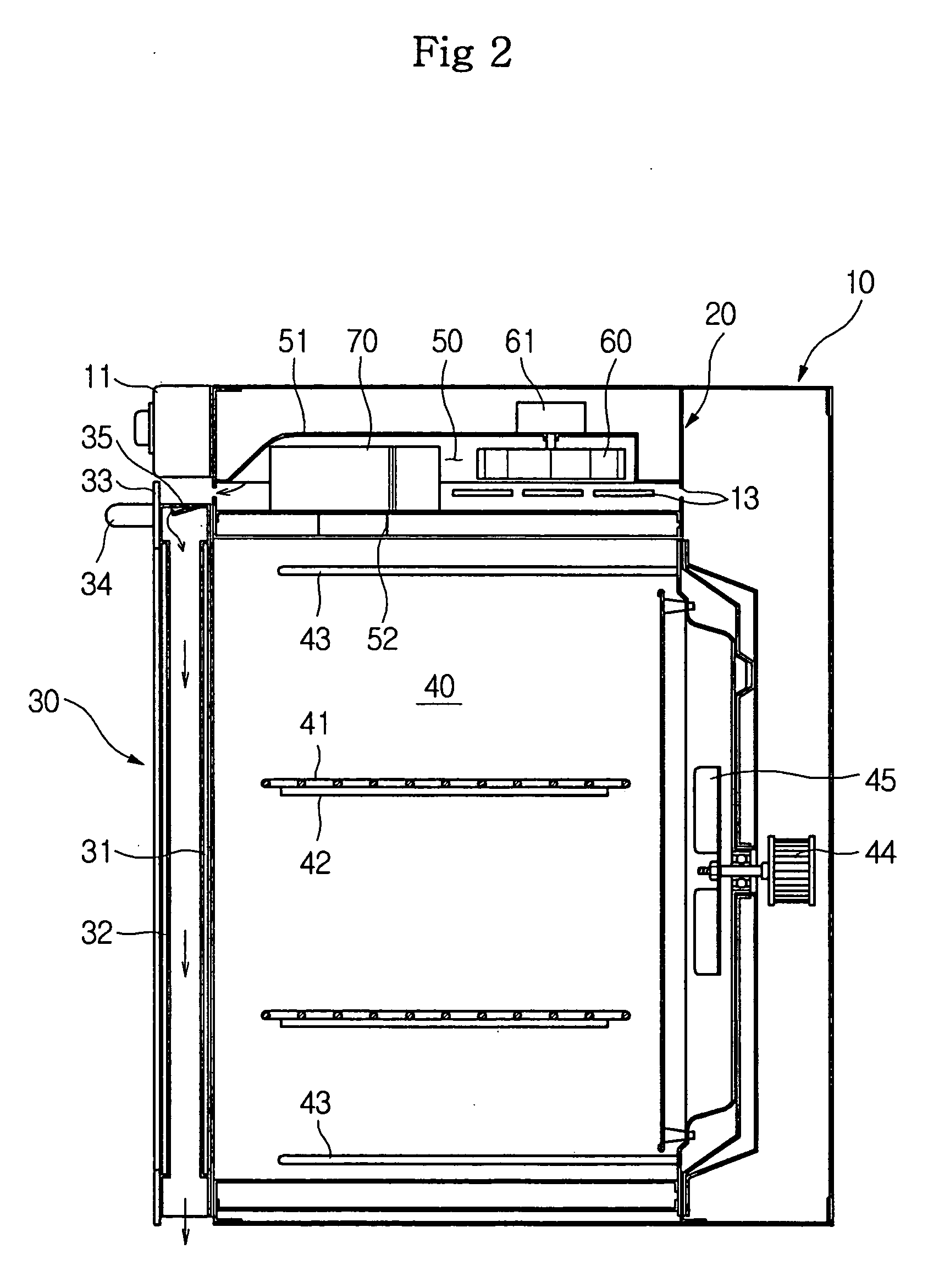
[0029]FIGS. 1-3 are views illustrating an oven according to the first embodiment of the present invention, in which FIGS. 1 and 2 are a front view and a elevation sectional view of the oven according to the first embodiment of the present invention and FIG. 3 is a sectional view illustrating a discharge of hot air generated from a cooking chamber and separated from air for cooling a cooking chamber door.

[0030] As shown in FIGS. 1-3, the oven according to the first embodiment of the present invention comprises an open-front box-shaped outer case 10, an open-front box shaped inner case 20 accommodated in the outer case 10, and a door hinged to the lower side of the in...


PUM


Abstract

An oven, effectively and rapidly cooling a door by passing a sufficient quantity of cooling air through the door, is disclosed. The oven includes an outer case, an inner case, a door opening and closing the inner case, and a blower chamber having a cooling fan and provided at the upper side of the inner case. The door includes an inner plate and a frame to form an opened lower end. The frame has holes formed in the upper side to flowing air discharged by the cooling fan between the inner plate and an outer plate. A vent hole communicating with the blower chamber is provided in the upper end of the cooking chamber to pass hot air of the cooking chamber through the vent hole. Around the vent hole, a partition member is provided for preventing the hot air from being mixed with air discharged by cooling fan.

Description

CROSS-REFERENCE TO RELATED APPLICATIONS [0001] This application claims the benefit of Korean Patent Application No. 2005-17417, filed on Mar. 2, 2005, in the Korean Intellectual Property Office, the disclosure of which is incorporated herein by reference. BACKGROUND OF THE INVENTION [0002] 1. Field of the Invention [0003] The present invention relates to an oven, and more particularly, to an oven for rapidly cooling a cooking chamber door. [0004] 2. Description of the Related Art [0005] Generally, ovens are structured to heat a cooking chamber using electricity or gas to cook food placed in the cooking chamber. Since the cooking chamber of the oven is maintained at a high temperature when cooking food, a door for opening and closing the cooking chamber is also heated to a high temperature. [0006] Thus, for safety, the oven should have a structure to cool the door under a prescribed temperature. For example, U.S. Pat. No. 3,889,099 discloses a structure to cool a door using a cooling...

Claims


Application Information

Patent Timeline
Patent Type & Authority Applications(United States)
IPC IPC(8): F24C15/04
CPCF24C15/006F24C15/04F24C15/2007
Inventor KIM, KYUOUNG HOHWANG, YUN ICHONG, SEOK WEONCHO, PUNG YEUNHA, YU JEUBPARK, SUNG SOOKIM, SUNG KWANGLEE, KIL YOUNGKIM, CHEOL JINKIM, TAE HOKANG, SANG HYUN
Owner SAMSUNG ELECTRONICS CO LTD
Why Eureka
Try Eureka