
Tensioning device

a technology of a stent and a stent body, which is applied in the direction of valve details, valve arrangements, slide valves, etc., can solve the problems of increased leakage, difficulty or inability to reduce the gap, and preventing the entire flow of fluid, so as to achieve the effect of reducing the gap

Inactive Publication Date: 2006-09-07
ROSS VALVE MFG
View PDF7 Cites 2 Cited by
  • Summary
  • Abstract
  • Description
  • Claims
  • Application Information

AI Technical Summary

Benefits of technology

[0009] The present invention provides a tensioning device capable of reducing the gap between proximate plates in a valve mechanism and thereby reducing or preventing the leakage of fluid through a valve. A first aspect of the invention provides a valve mechanism comprising a valve body, a first plate having at least one opening, a second plate having at least one opening and residing proximate the first plate, and a tensioning device for decreasing a gap between a surface of the first plate and a surface of the second plate.
[0011] A third aspect of the invention provides a tensioning device comprising a ring member capable of placement proximate a movable valve component, and a tensioning member, wherein the tensioning member is capable of engaging the ring member and a fixed valve component to reduce a gap between the ring member and the movable valve component.

Problems solved by technology

One problem with such mechanisms, however, is that it is often difficult or impossible to reduce the gap between proximate plates to such a degree that fluid flow is entirely prevented.
Such leakage is more severe where the fluid delivery system is operated under pressure.

Method used


Image

  • Tensioning device
  • Tensioning device
  • Tensioning device

Examples


Embodiment Construction

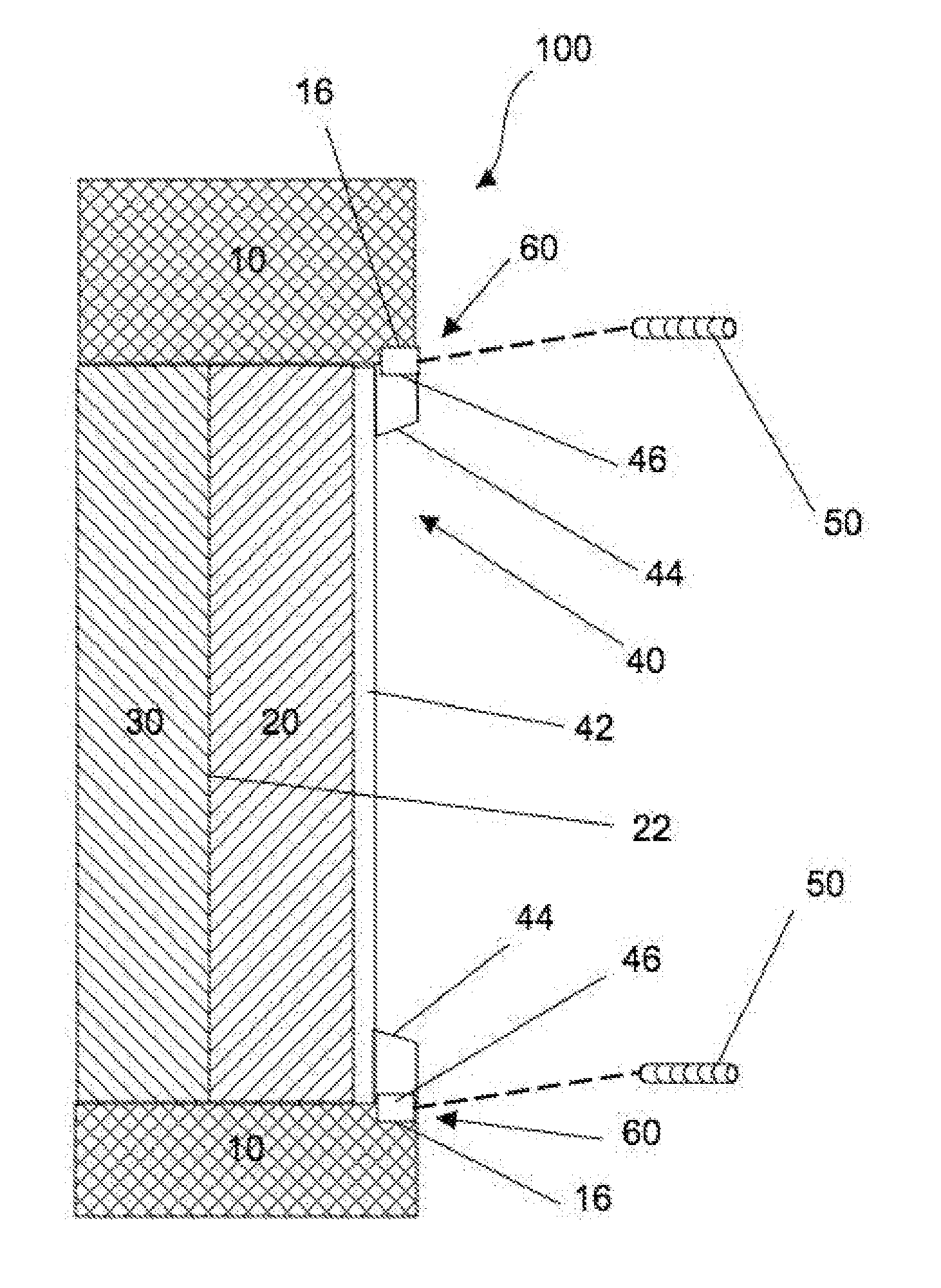
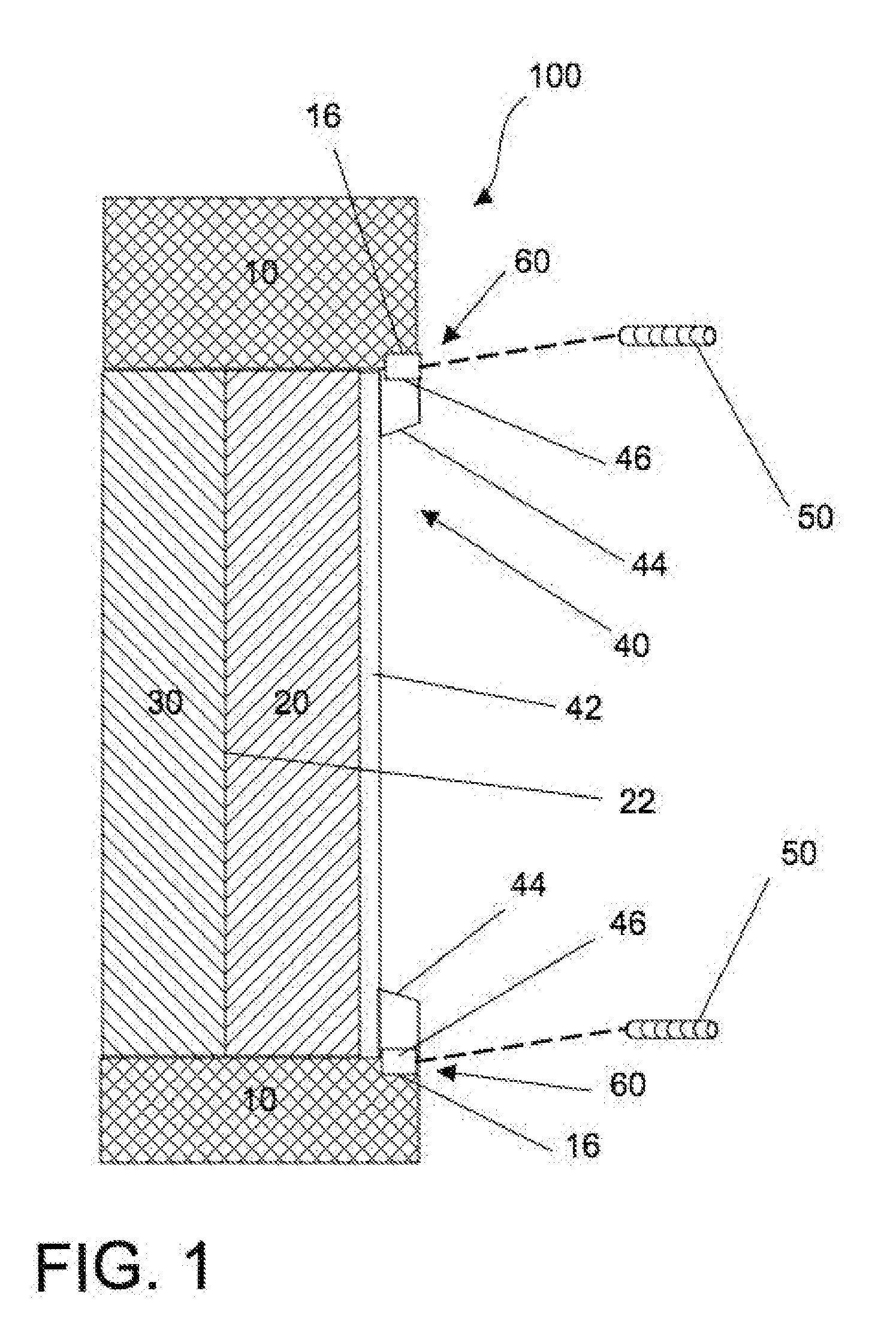
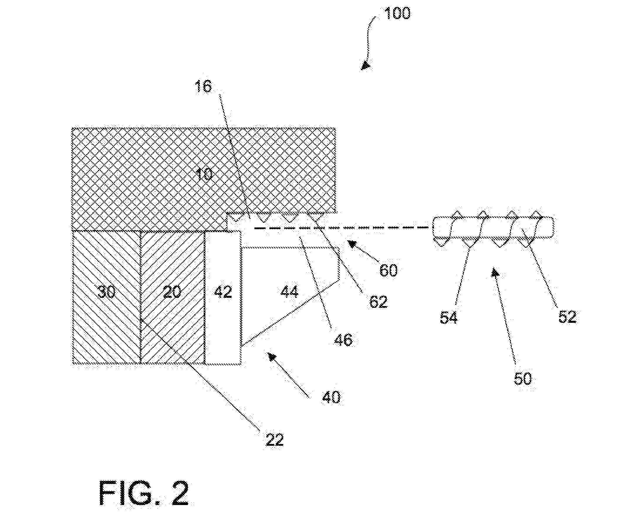
[0017] Referring to FIG. 1, a valve mechanism 100 according to the present invention is shown comprising a valve body 10, a first plate 20, a second plate 30, a ring member 40, and a tensioning member 50. First plate 20 and second plate 30 are proximally-located, usually with a gap 22 between.

[0018] Ring member 40 is located proximate first plate 20. As shown, ring member 40 comprises a ring body 42 and one or more attachment body 44. While described as a ring, it should be noted that ring member 40 may be of any of a number of shapes. Generally, the shape of ring member 40 approximates that of first plate 20 and may be square, rectangular, triangular, octagonal, etc. Similarly, while ring member 40 is shown as comprising distinct parts (ring body 42 and attachment body 44), it should be appreciated that ring member 40 may comprise a single element capable of performing the functions of both, as described below.

[0019] Gap 22 may be reduced or eliminated, by tensioning ring member ...


PUM


Abstract

The present invention provides a tensioning device capable of reducing the gap between proximate plates in a valve mechanism and thereby reducing or preventing the leakage of fluid through a valve. A first aspect of the invention provides a valve mechanism comprising a valve body, a first plate having at least one opening, a second plate having at least one opening and residing proximate the first plate, and a tensioning device for decreasing a gap between a surface of the first plate and a surface of the second plate.

Description

CROSS REFERENCE TO RELATED APPLICATIONS [0001] This is a continuation of International Application PCT / US2004 / 039601, with an International Filing Date of Nov. 24, 2004, currently pending, which claims priority to U.S. Provisional Patent Application 60 / 525,404, filed Nov. 26, 2003, both of which are hereby incorporated by reference herein.BACKGROUND OF THE INVENTION [0002] (1) Technical Field [0003] The present invention relates generally to tensioning devices and more particularly to devices for increasing tension between valve components. [0004] (2) Related Art [0005] Valve devices have long been used to control the flow of fluids (i.e., liquids and gasses) within fluid delivery systems. Most often, valve devices are used to open or close a portion of the delivery system to the flow of a fluid. Such opening and closing may be partial, e.g., to regulate the rate of fluid flow, or complete. [0006] Various internal valve mechanisms have been employed for such purposes, including, for...

Claims


Application Information

Patent Timeline
Patent Type & Authority Applications(United States)
IPC IPC(8): F16K25/00F16K3/18
CPCF16K3/18
Inventor BATCHER, RONALD H.ROSS, WILLIAM F.
Owner ROSS VALVE MFG
Learn More