
Multi-dimensional antenna in RFID system for reading tags and orientating multi-dimensional objects

a multi-dimensional antenna and tag technology, applied in the field of radio frequency identification (rfid) readers, can solve the problems that rfid readers cannot distinguish the orientation of three-dimensional jigsaw units between right and wrong, so as to achieve simple and easy operation

Inactive Publication Date: 2006-09-07
G TIME ELECTRONICS
View PDF3 Cites 26 Cited by
  • Summary
  • Abstract
  • Description
  • Claims
  • Application Information

AI Technical Summary

Benefits of technology

[0009] Another object of the present invention is to provide a simple and easy way to position Tags and antennas in particular positions in order to distinguish the orientation of multi-dimensional objects.

Problems solved by technology

Therefore, the RFID reader could not distinguish the orientation of the three-dimensional jigsaw unit between right and wrong because the modulated radio signals are non-direction signals.
In other words, the RFID reader could not distinguish the orientation of the three-dimensional jigsaw unit between right and wrong even though the three-dimensional jigsaw unit aims at the right position.

Method used


Image

  • Multi-dimensional antenna in RFID system for reading tags and orientating multi-dimensional objects
  • Multi-dimensional antenna in RFID system for reading tags and orientating multi-dimensional objects
  • Multi-dimensional antenna in RFID system for reading tags and orientating multi-dimensional objects

Examples


Embodiment Construction

[0019] In the following detailed description of the preferred embodiments, reference is made to the accompanying drawings which form a part hereof, and in which is shown by way of illustration specific embodiments in which the invention may be practiced. In this regard, directional terminology, such as “top,”“left,”“right,”“bottom,” etc., is used with reference to the orientation of the Figure(s) being described. As such, the directional terminology is used for purposes of illustration and is in no way limiting. It is to be understood that other embodiments may be utilized and structural or logical changes may be made without departing from the scope of the present invention.

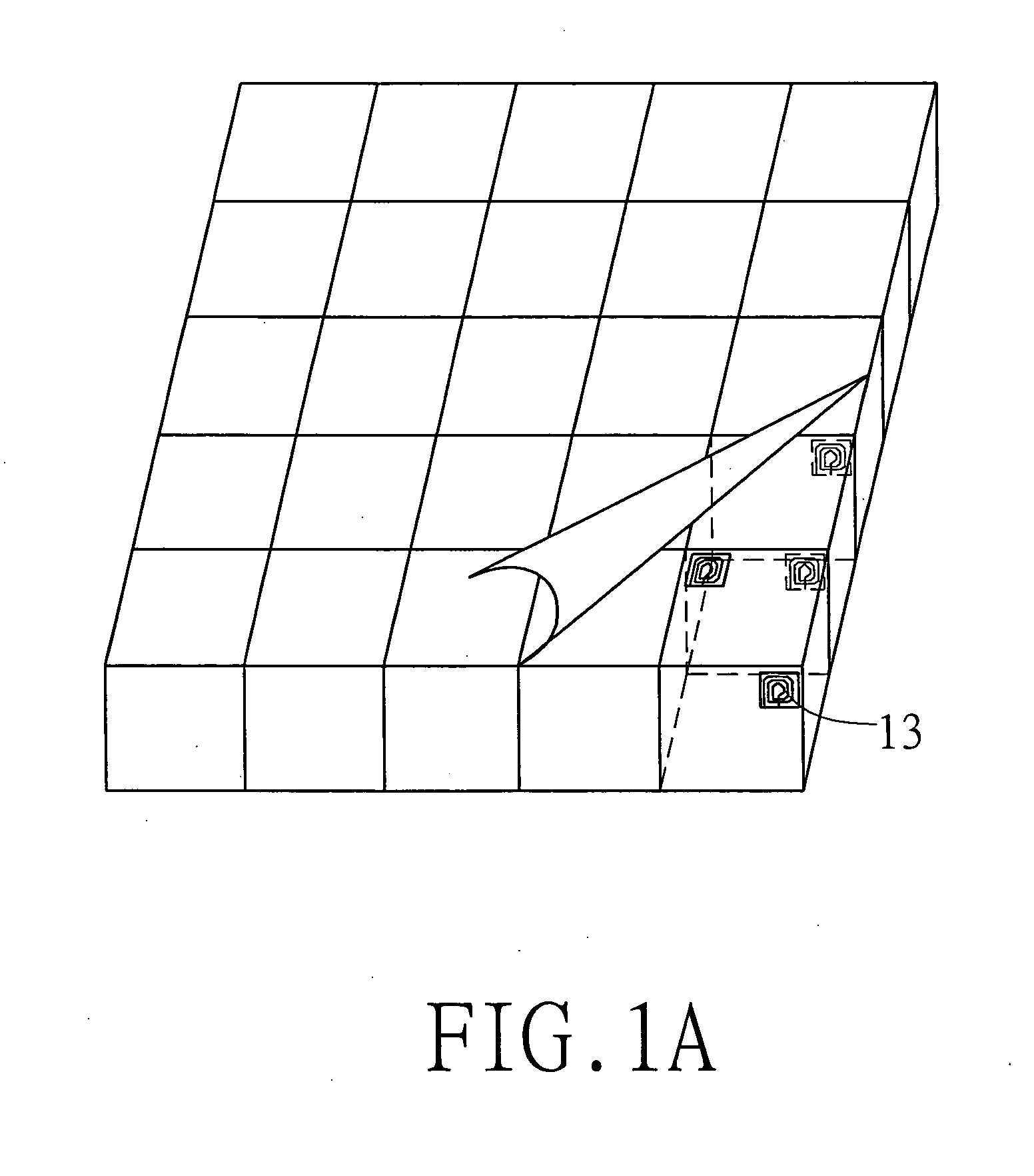
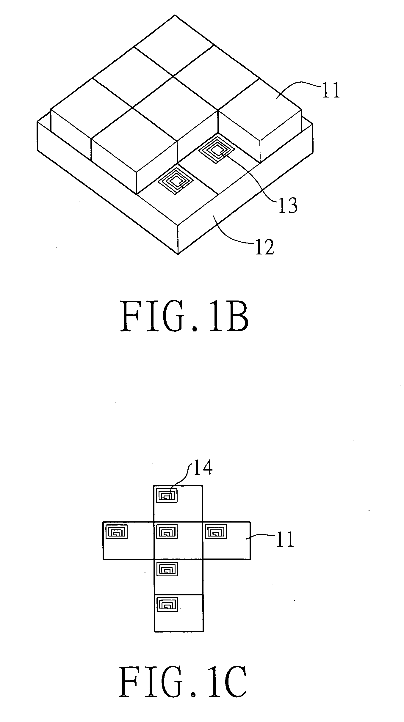
[0020] Since the U.S. patent application Ser. No. 11 / 062,815, filed on Feb. 23, 2005, which discloses a RFID reader having a multi-dimensional antenna array, description thereof is not to be further detailed herein. Please Refer to FIGS. 1A-1C, which show a schematic diagram of a three-dimensional jigsaw utiliz...


PUM


Abstract

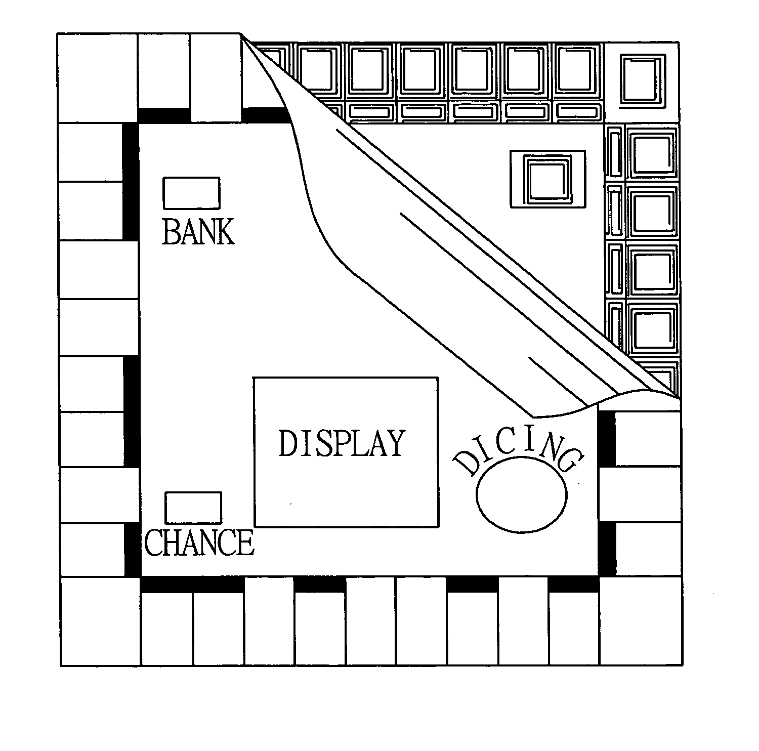
A RFID system applying to a three-dimensional jigsaw is provided. The RFID system includes a jigsaw substrate having a plurality of blocks, a plurality of jigsaw units corresponding to each blocks of the jigsaw substrate, a RFID reader having a plurality of antennas positioned in a position of each blocks of the jigsaw substrate, and a plurality of tags positioned in a position of each face of a three-dimensional jigsaw unit corresponding to the positions of the antennas, wherein the RFID reader communicates to the tags using modulated radio signals through the antennas and the tags respond with modulated radio signals in order to determine whether the orientation of the three-dimensional jigsaw unit is correct or not.

Description

CROSS-REFERENCE TO RELATED APPLICATIONS [0001] This is a continuation-in-part application that claims the benefit of priority under 35 U.S.C. s.119 to a non-provisional application, application Ser. No. 11 / 062,815, filed Feb. 23, 2005.BACKGROUND OF THE PRESENT INVENTION [0002] 1. Field of Invention [0003] The present invention relates to a radio frequency identification (RFID) reader using a plurality of antennas for reading data from Tags, and more particularly to a RFID reader using a plurality of antennas applied to multi-dimensional objects, such as three-dimensional jigsaw with multimedia sound and light effect, to distinguish the orientation of the three-dimensional jigsaw unit between right and wrong. [0004] 2. Description of Related Arts [0005] Radio Frequency Identification (RFID) systems are used for identification and / or tracking of equipment, inventory, or living things. RFID systems are radio communication systems that communicate between a radio transceiver, called a R...

Claims


Application Information

Patent Timeline
IPC IPC(8): G08B13/14
CPCG06K7/10336G06K7/10346
Inventor WU, CHE-MINGHOU, TIEN-FA
Owner G TIME ELECTRONICS
Learn More