
Two blade scraping device

a scraping device and two-blade technology, applied in the direction of carpet cleaners, household cleaners, coatings, etc., can solve the problems of inconvenient storage within the automobile, limited in their usefulness, and too large to be practical for small surfaces such as rear-view mirrors, so as to achieve convenient storage of the device, reduce operator strokes, and reduce the effect of aging

Inactive Publication Date: 2006-09-14
BYRNES JAMES MICHAEL
View PDF14 Cites 25 Cited by
  • Summary
  • Abstract
  • Description
  • Claims
  • Application Information

AI Technical Summary

Benefits of technology

[0006] The device is a handheld manual-powered scraping tool employing a pivotable multi blade head for removing material from a work surface. This scraper which employs two blade elements set at the appropriate relative angle to allow scraping in push and pull directions provides efficiency advantages over a scraper using a single blade. In the preferred embodiment, mounting the two blade head onto a handle that can pivot independently from the head provides ergonomic and functional advantages over a conventional fixed head scraper by maintaining the most efficient scraping angle of blades relative to the work surface independently of the operators preferred handle holding position. The pivoting head is configured with intentionally flexible blade elements to allow the blades to conform to the work surface, thereby allowing fewer operator strokes when the device is used to remove material from a curved surface such as ice from automobile glass. The device also provides a means to stow the pivotable head in a collapsed configuration to allow convenient storage of the device and to provide a means to protect the blades from damage when not in use. In the preferred embodiment, a central fixed third blade allows scraping of smaller surfaces such as automobile rearview mirrors when the device is configured for ice removal.

Problems solved by technology

Although all may be functional by design, they cannot be stowed conveniently within the automobile and are limited in their usefulness due to their implied size and in some cases to the inflexibility of the blades.
If they are sized for scraping larger surfaces such as windshields, they would be too large to be practical for use on small surfaces such as rear-view mirrors, nor could they be stowed in a typical sized car door pocket.
Most of the other devices with related patents provide a rigid scraping blade which is ineffective for conforming to non-flat surfaces such as automobile glass.

Method used


Image

  • Two blade scraping device
  • Two blade scraping device
  • Two blade scraping device

Examples


Embodiment Construction

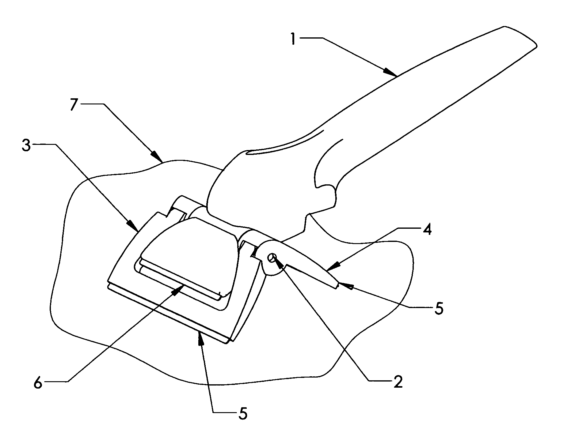
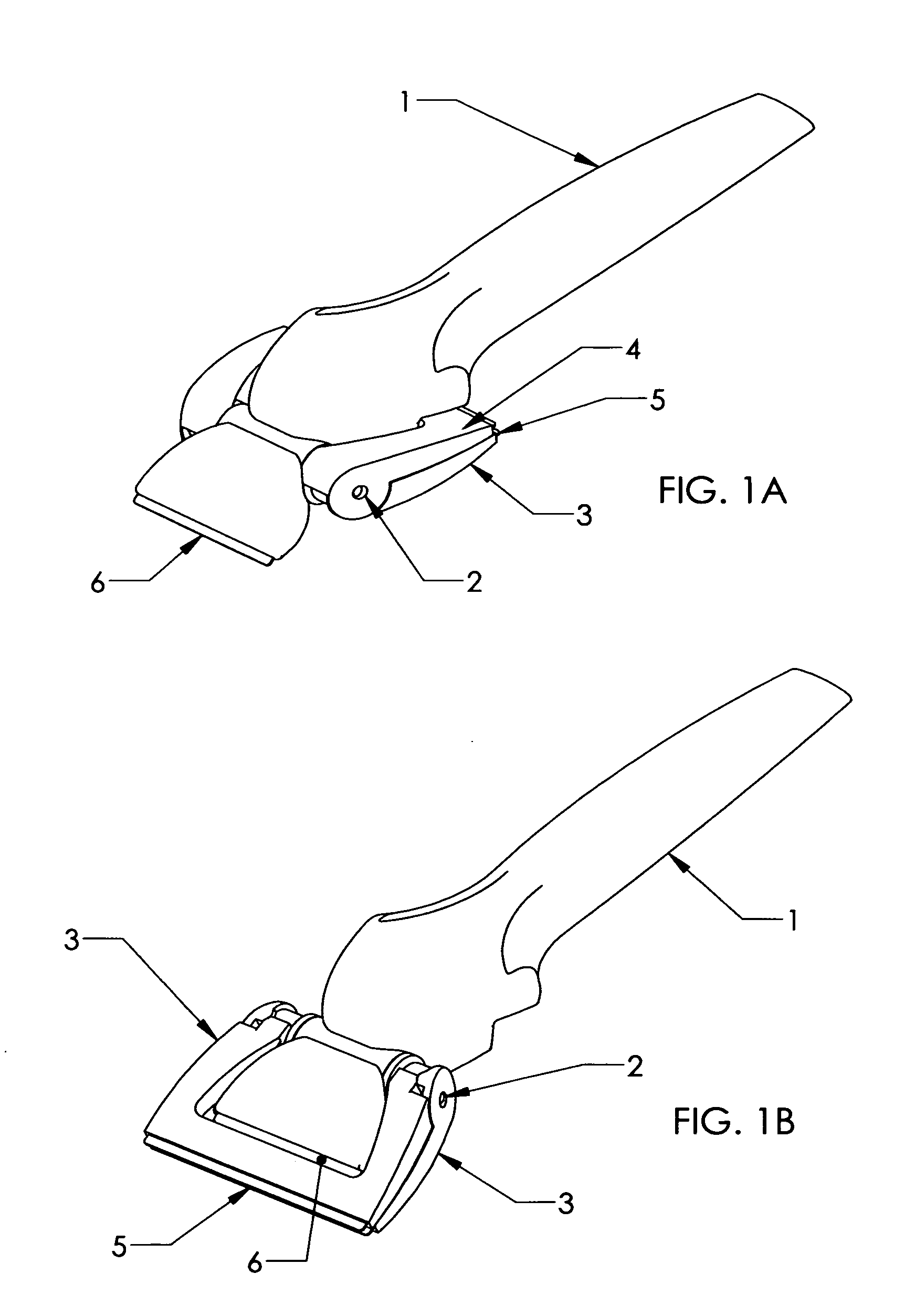
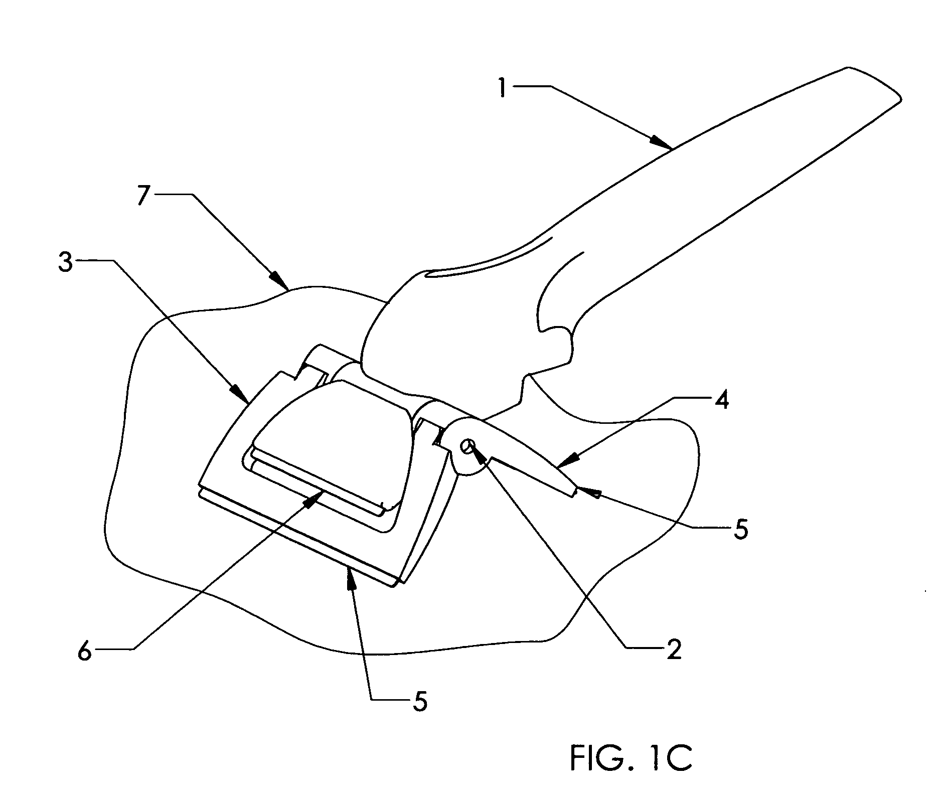
[0029] Referring to FIG. 1C, the scraping device consists of a handle 1, a pivot shaft 2, and two planar scraping elements 3 and 4. Optionally, the scraping elements 3 and 4 may be augmented with item 5 blades affixed to their scraping edges to facilitate removal of material from the work surface 7. Also a fixed scraping blade item 6 may be affixed to either end of the handle 1 as an additional scraping element to be used independently from scraping elements 3 and 4. FIGS. 1A,B,C and 2 are views of the preferred embodiment FIG. 1A is a view of the device in the stowed back configuration for storage or for scraping with the fixed blade element 6. FIG. 1B is a view demonstrating the capability of stowing the scraping elements 3, 4 in a forward alternate configuration advantageous for certain scraping applications. FIG. 1C is a view of the device in the deployed configuration for scraping with the pivotable blade elements 3 and 4.

[0030] The scraping elements 3 and 4 are related in sha...


PUM


Abstract

A hand-held scraper device containing a stowable multi blade pivoting head. The pivoting head is comprised of at least two scraping elements which remain at a fixed angle relative to each other while still allowing a pivoting action of the head assembly independently from the handle. The angle of the scraping elements relative to each other is set such that as the two scraping elements are jointly presented against the work surface they will be maintained at an angular attitude conducive to a scraping action in both a push and pull direction. The pivoting head can be collapsed for more efficient stowage or as an alternate configuration for specific scraping applications.

Description

REFERENCE TO RELATED APPLICATIONS [0001] This application is entitled to the benefit of Provisional Patent Application no. 60 / 661,371, filed Mar. 14, 2005.FIELD OF THE INVENTION [0002] This device relates to a handheld manual-powered scraping tool employing a pivotable and stowable head for removing material from a work surface. BACKROUND OF THE INVENTION [0003] There have been more than 200 patents granted over the years for devices of a wide variety of forms intended to be used for human powered removal of material from a surface through the use of scraping action. One of the most common commercial usages of these devices has focused on the removal of ice from automobile windshields. Although there have been several improvements over time related to their performance, ergonomics, and ease of use, the author believes there are additional attributes and novel features that would further improve upon the functionality and commercial viability of these devices. [0004] There have been ...

Claims


Application Information

Patent Timeline
IPC IPC(8): A47L13/08
CPCA47L1/16A47L13/022A47L13/08B44D3/162
Inventor BYRNES, JAMES MICHAEL
Owner BYRNES JAMES MICHAEL
Learn More