Method for determining a zero-point error in a vibratory gyroscope

a vibratory gyroscope and zero-point error technology, applied in the field of coriolis gyros, can solve the problems of inability to prevent other natural oscillations, inability to differentiate between the two parts,

Active Publication Date: 2006-09-14
NORTHROP GRUMMAN SYST CORP +1
View PDF9 Cites 21 Cited by
  • Summary
  • Abstract
  • Description
  • Claims
  • Application Information

AI Technical Summary

Problems solved by technology

As a result of mechanical structure and unavoidable manufacturing tolerances, it is impossible to prevent other natural oscillations, in addition to the stimulating oscillation and the read oscillation, of

Method used


Image

  • Method for determining a zero-point error in a vibratory gyroscope
  • Method for determining a zero-point error in a vibratory gyroscope
  • Method for determining a zero-point error in a vibratory gyroscope

Examples


Embodiment Construction

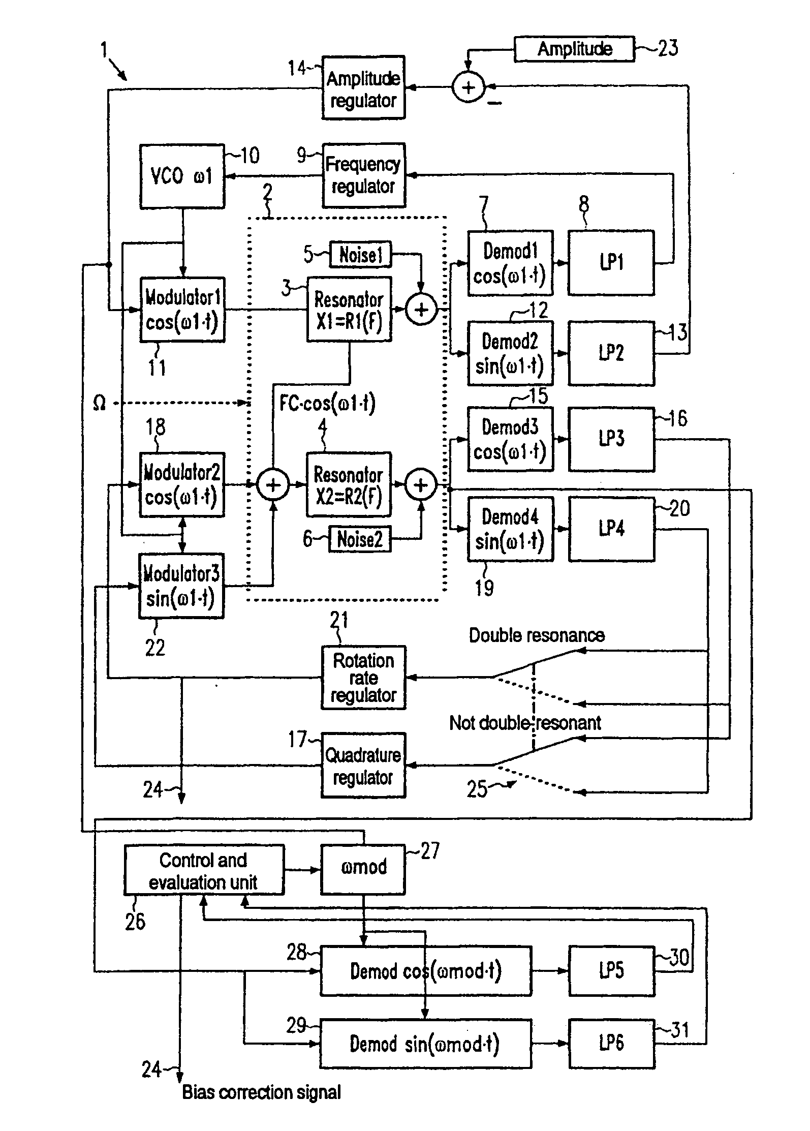
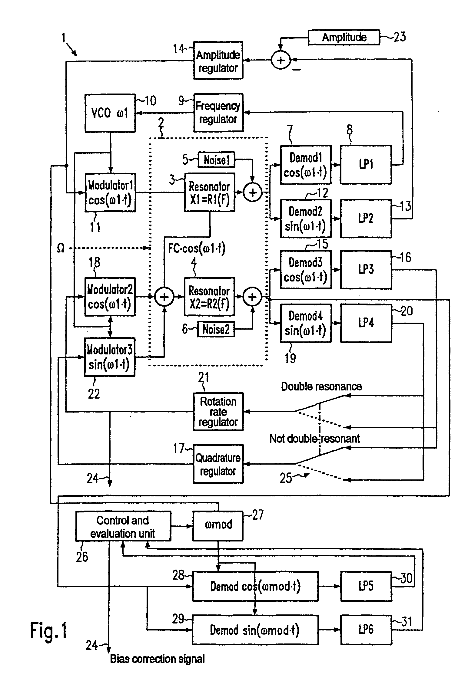
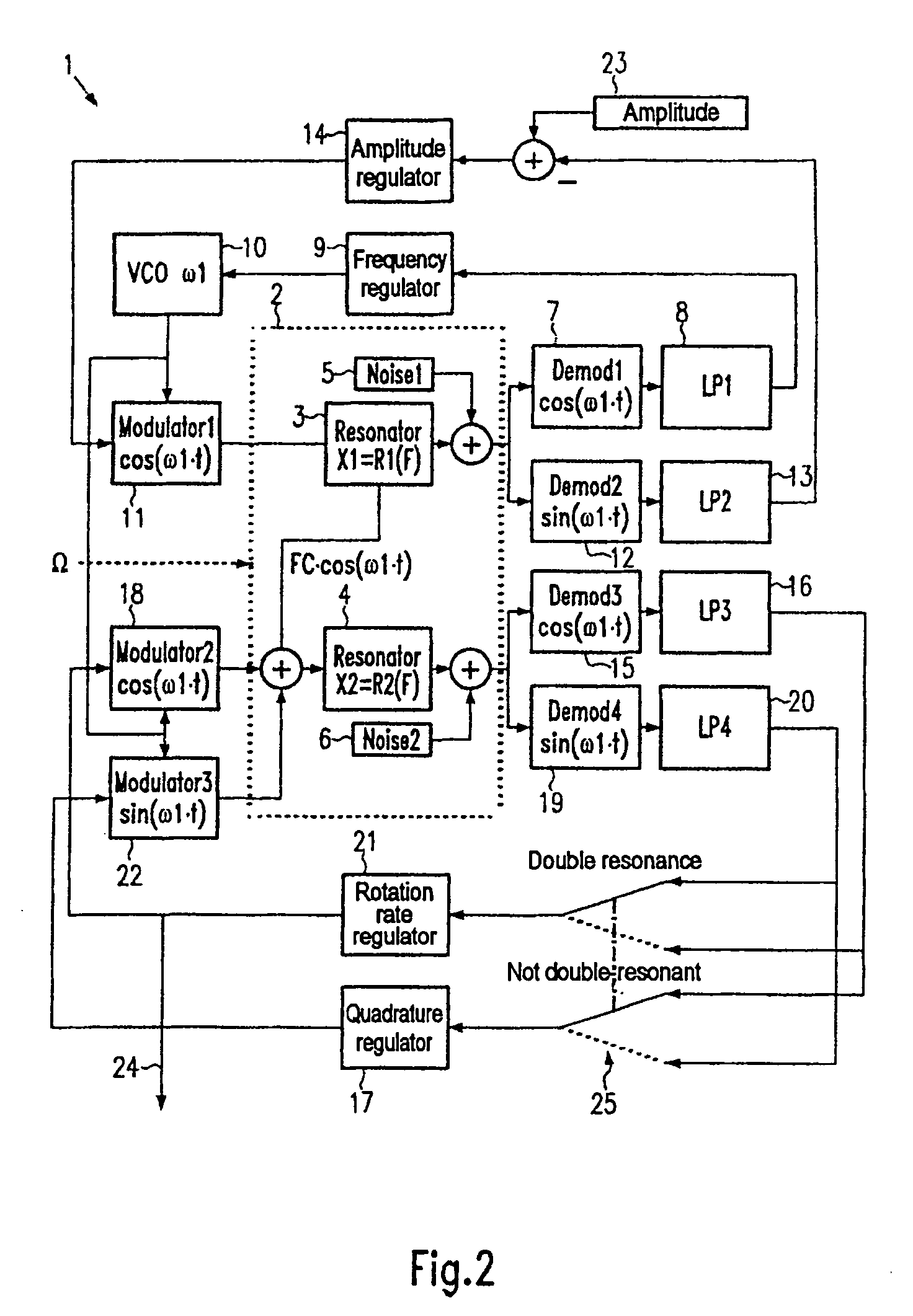
[0024]FIG. 1 is a schematic diagram of a Coriolis gyro in accordance with the present invention. In it, parts and devices which correspond to those of the prior art device of FIG. 2 are indicated by identical reference symbols and not discussed below. The method of the invention will be explained below with reference to FIG. 1.

[0025] A reset Coriolis gyro includes a control and evaluation unit 26, a modulator 27 (disturbance unit) having a variable frequency ωmod and, preferably an adjustable amplitude, demodulators 28, 29 that operate in quadrature at the frequency ωmod, and fifth and sixth low-pass filters 30 and 31. The disturbance unit 27 produces an alternating signal at the frequency ωmod. This is added to the force input of the stimulating oscillation (first resonator 3). The signal is also supplied as a reference signal to the demodulators 28, 29. An alternating force, corresponding to the alternating signal, is thus additionally applied to the resonator 2. Such alternating...


PUM


Abstract

A method for determination of the zero error of a Coriolis gyro. Appropriate disturbance forces are applied to the resonator of the Coriolis gyro such that at least one natural oscillation of the resonator is stimulated that differs from the stimulating and read oscillations. A change in a read signal which represents the read oscillation and results from the stimulation of the at least one natural oscillation is determined as a measure of the zero error.

Description

BACKGROUND [0001] 1. Field of the Invention [0002] The present invention relates to Coriolis gyros. More particularly, this invention pertains to a method for determination of a zero error in a Coriolis gyro. [0003] 2. Description of the Prior Art [0004] Coriolis gyros (also referred to as “vibration gyros”) are in increasing use for navigation. They possess a mass system that is caused to oscillate with the oscillation generally being the superposition of a large number of individual oscillations. [0005] The individual oscillations of the mass system are initially independent of one another and can be referred to abstractly as “resonators”. At least two resonators are required for operation of a vibration gyro: one (the first resonator) is artificially stimulated to oscillate, and this is referred to below as the “stimulating oscillation”. The other (the second resonator) is stimulated to oscillate only when the vibration gyro is moved / rotated. This is because Coriolis forces occur...

Claims


Application Information

Patent Timeline
IPC IPC(8): G01C25/00G01C19/56G01C
CPCG01C19/56G01C25/00G01C19/5776
Inventor SCHROEDER, WERNER
Owner NORTHROP GRUMMAN SYST CORP
Why Eureka
Try Eureka