Electrohydraulic braking system

a technology of electrohydraulic brakes and brake components, applied in brake systems, vehicle components, brake components, etc., can solve the problems of increasing the number of existing components, the effort and expense of assembly and installation space, and the increase of the number of potential errors

Active Publication Date: 2006-09-14
ROBERT BOSCH GMBH
View PDF22 Cites 21 Cited by
  • Summary
  • Abstract
  • Description
  • Claims
  • Application Information

AI Technical Summary

Problems solved by technology

This increases the number of existing components as well as the effort and expense of assembly and th

Method used


Image

  • Electrohydraulic braking system
  • Electrohydraulic braking system

Examples


Embodiment Construction

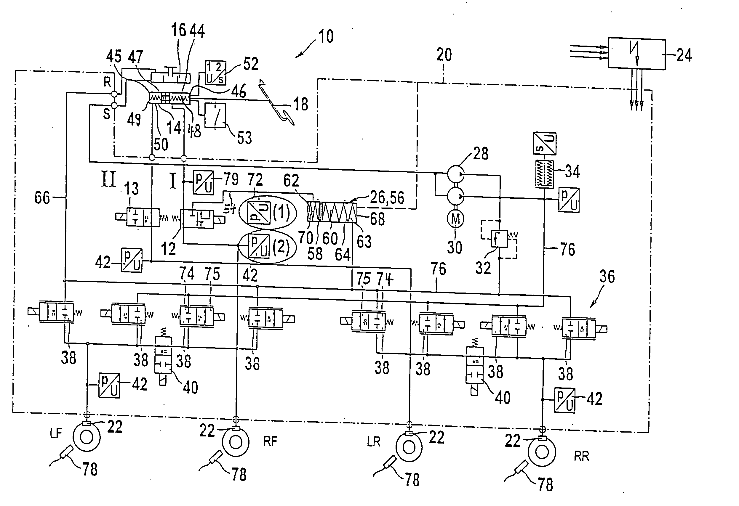
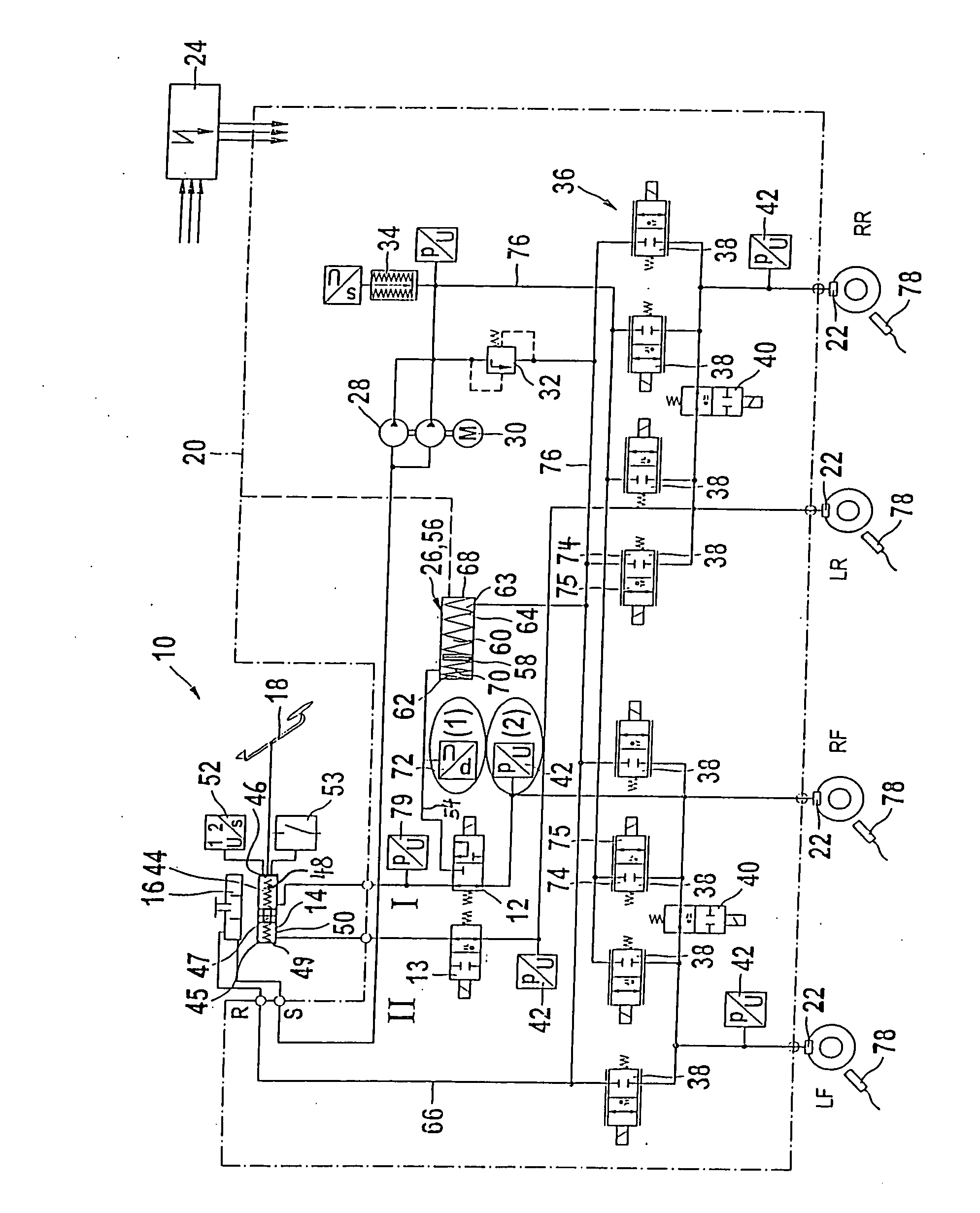
[0005] The electrohydraulic brake system 10 of the invention, shown in the drawing, includes a muscle-force-actuatable auxiliary brake and an external-force-actuatable service brake. Both partial systems of these brake systems utilize common components but are separated from one another by so-called operating mode switchover valves 12, 13. The auxiliary brake is active only in the event of a malfunction of the service brake.

[0006] The electrohydraulic brake system 10, besides a master cylinder 14 with a closed container 16 for brake fluid and an actuating unit in the form of a brake pedal 18 that can be actuated by the driver using muscle force, has a hydraulic unit 20 for controlling the brake pressures in a total of four wheel brakes 22, connected to this hydraulic unit 20, as well as an electronic control unit 24, which electrically triggers the components of the hydraulic unit 20. The wheel brakes 22 are identified by the letters VL, VR, HL and HR, in accordance with their loca...


PUM


Abstract

An electrohydraulic brake system having a muscle-force-actuatable auxiliary brake and an external-force-actuatable service brake includes operating mode switchover valves triggerable by an electronic control unit for switching from the service braking state to the auxiliary braking state. A piston/cylinder unit with a pressure medium connection between a master cylinder and a wheel brake which is interrupted by the switchover valves to simulate the pedal travel in the service braking state. The piston/cylinder receives the pressure medium displaced in the master cylinder by actuation of the brake pedal by the driver's foot. The piston/cylinder unit can be hydraulically blocked in the auxiliary braking state so that pressure medium positively displaced in the master cylinder is available to the greatest possible extent for building up pressure at the wheel brakes. The subjection of the piston/cylinder unit to pressure medium is controlled via one of the operating mode switchover valves.

Description

BACKGROUND OF THE INVENTION [0001] The invention is based on an electrohydraulic brake system as generically defined by the preamble to claim 1. A brake system of this type has already been disclosed, for instance in German Patent Disclosure DE 196 36 432 A1. This known brake system has a muscle-force-actuatable auxiliary brake and an external-force-actuatable service brake. For switching the brake system over from the service braking state to the auxiliary braking state, such brake systems have operating mode switchover valves, which are triggerable by an electronic control unit. Moreover, for simulating the pedal travel in the service braking state of the brake system, in which a pressure medium connection between a master cylinder and a wheel brake is interrupted by the aforementioned operating mode switchover valves, there is a piston / cylinder unit. It receives the volume of pressure medium positively displaced in the master cylinder by the actuation of the brake pedal by the dr...

Claims


Application Information

Patent Timeline
IPC IPC(8): B60T8/40B60T13/14
CPCB60T8/4081B60T13/145
Inventor GOTTWICK, ULRICHKUNZ, MICHAEL
Owner ROBERT BOSCH GMBH
Why Eureka
Try Eureka