Apparatus for displaying an image
a technology for displaying images and apparatuses, applied in the field of apparatuses for displaying images, can solve the problems of complicated operations to select any of these images to be displayed, and achieve the effect of quick selection of the desired imag
- Summary
- Abstract
- Description
- Claims
- Application Information
AI Technical Summary
Benefits of technology
Problems solved by technology
Method used
Image
Examples
first embodiment
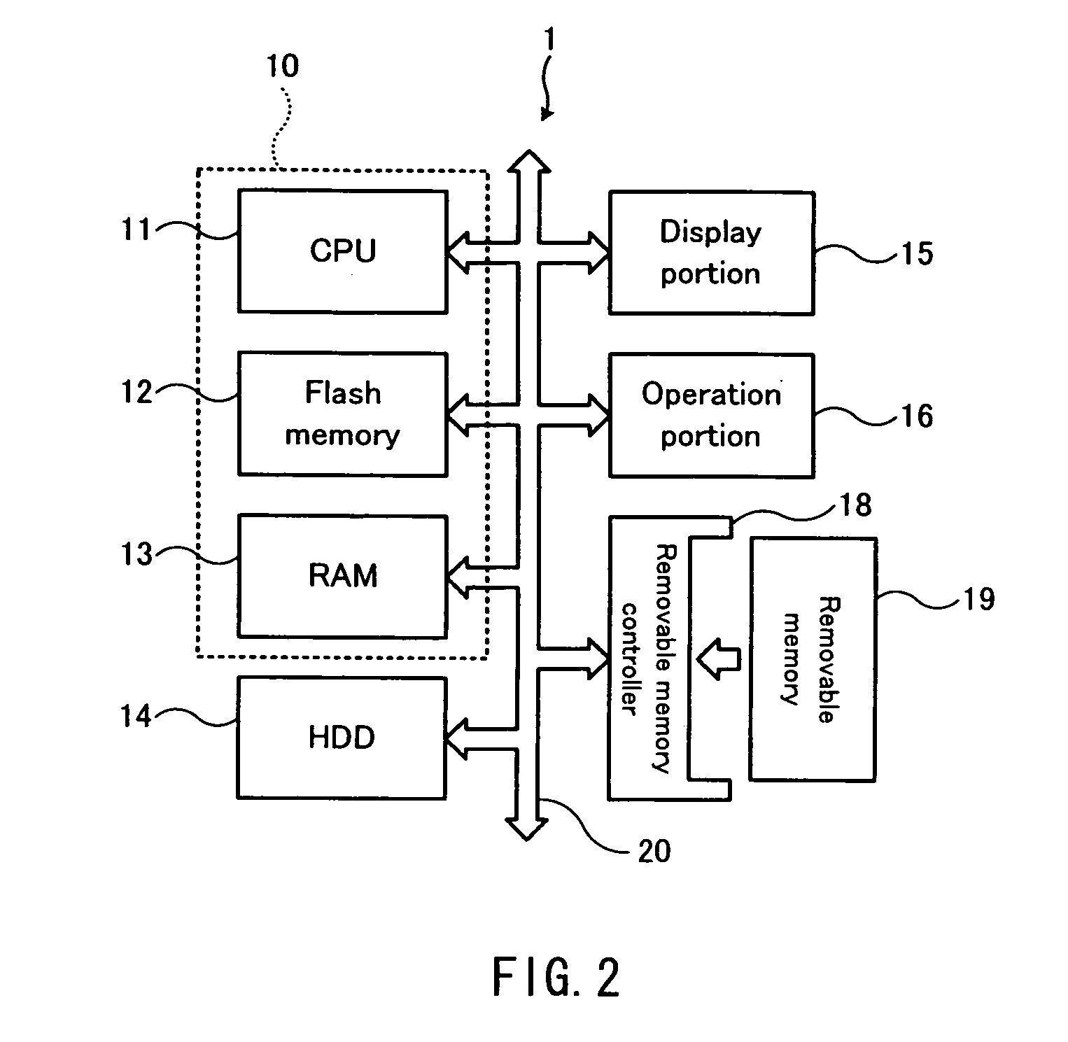
[0043]FIG. 2 is a block diagram showing a hardware configuration of an image reproducer 1 related to the first embodiment of the present invention. The image reproducer 1 comprises a CPU11, a flash memory 12, an RAM13, a Hard Disk Drive (HDD) 14, a display portion 15., an operation portion 16, and a removable memory controller 18, wherein they are mutually connected through a bus 20. The image reproducer 1 as an apparatus for displaying an image is an electronic apparatus for reading images photographed by a DSC, etc. and stored in a removable memory 19, accumulating them in the HDD14, and displaying them at the display portion 15. It is to be noted that the apparatus for displaying an image may be a DSC, a communication apparatus equipped with an display device such as a cell phone, a Personal Digital Assistance (PDA), or a portable terminal unit such as an electronic book terminal.
[0044] A control portion 10 includes the CPU11, the flash memory 12, the RAM13 and the like. The CPU...
second embodiment
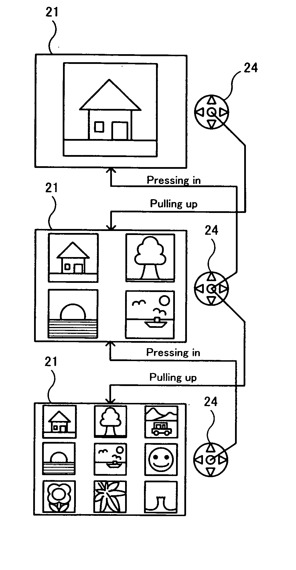
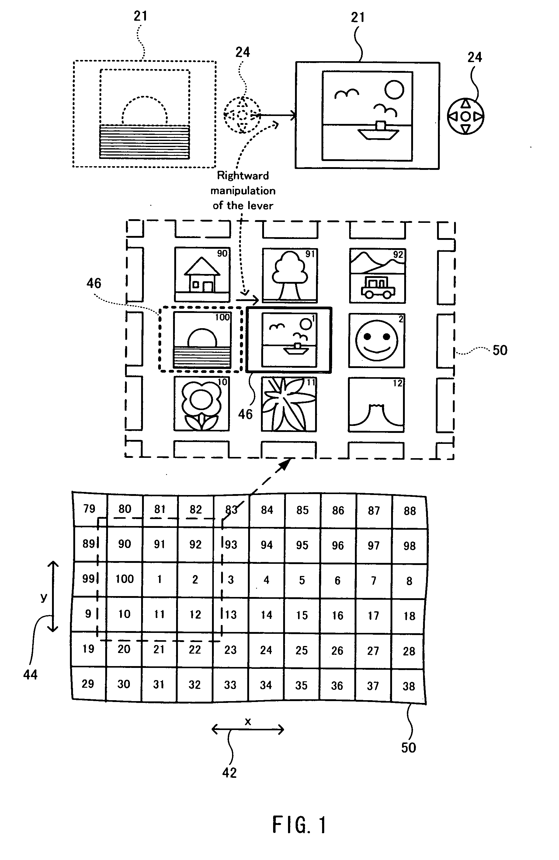
[0066] In an image reproducer 2 according to a second embodiment, a UI module 30 receives an manipulation of pressing in the lever 24 and that of pulling it up as commands to select images whose order numbers are 100 behind and 100 ahead the currently displayed image respectively, in addition to the commands related to the first embodiment. These commands correspond to “third command” described in the claim, a numeral of 100 as a difference in order number between the thus selected image whose order number is 100 behind or ahead and the currently displayed image corresponds to “second value”. Further, the lever 24 related to the second embodiment functions also as third input means.
[0067] Thus, in the image reproducer 2, it is possible to realize such a user interface that in response to a manipulation of pressing the lever 24 in and a manipulation of pulling it up, a display-subject area may apparently move between a limitless two-dimensional array 50 and another limitless two-dim...
third embodiment
[0072]FIG. 12 is an explanatory schematic diagram of a reproduction mode of an image reproducer 3 according to a third embodiment.
[0073] As shown in (A1), screen display data of an image of a partial area of a limitless two-dimensional array 50 related to the above-described plurality of embodiments is stored in a predetermined area of an RAM13 of the image reproducer 3. The partial area as used herein refers to an area that includes at least an image currently displayed at an LCD21 and an image that can be selected and displayed by manipulating a lever 24 in this condition. A UI module 30 related to the third embodiment specifies a desired display-subject area (see a display-subject area 60a shown in (A1)) for this screen display data, to display a screen for that display-subject area at the LCD21 (see (B1)).
[0074] The UI module 30 continuously moves a display-subject area from a display-subject area (see the display-subject area 60a shown in (A1)) of an image currently displayed...
PUM
 Abstract
Description
Claims
Application Information
 - R&D
- Intellectual Property
- Life Sciences
- Materials
- Tech Scout
- Unparalleled Data Quality
- Higher Quality Content
- 60% Fewer Hallucinations
Browse by: Latest US Patents, China's latest patents, Technical Efficacy Thesaurus, Application Domain, Technology Topic, Popular Technical Reports.
© 2025 PatSnap. All rights reserved.Legal|Privacy policy|Modern Slavery Act Transparency Statement|Sitemap|About US| Contact US: help@patsnap.com


