Method for obtaining a position match of 3D data sets in a dental CAD/CAM system

a technology of 3d data and camera system, which is applied in image data processing, medical science, dentistry, etc., can solve the problems of poor scan quality and automatic process failur

Inactive Publication Date: 2006-09-14
SIRONA DENTAL SYSTEMS
View PDF24 Cites 73 Cited by
  • Summary
  • Abstract
  • Description
  • Claims
  • Application Information

AI Technical Summary

Benefits of technology

[0028] After execution of the first transformation, a second transformation is thus carried o

Problems solved by technology

There are cases in which this automatic process fails, due, for example, to the poor quality of the scans, too few

Method used


Image

  • Method for obtaining a position match of 3D data sets in a dental CAD/CAM system
  • Method for obtaining a position match of 3D data sets in a dental CAD/CAM system
  • Method for obtaining a position match of 3D data sets in a dental CAD/CAM system

Examples


Embodiment Construction

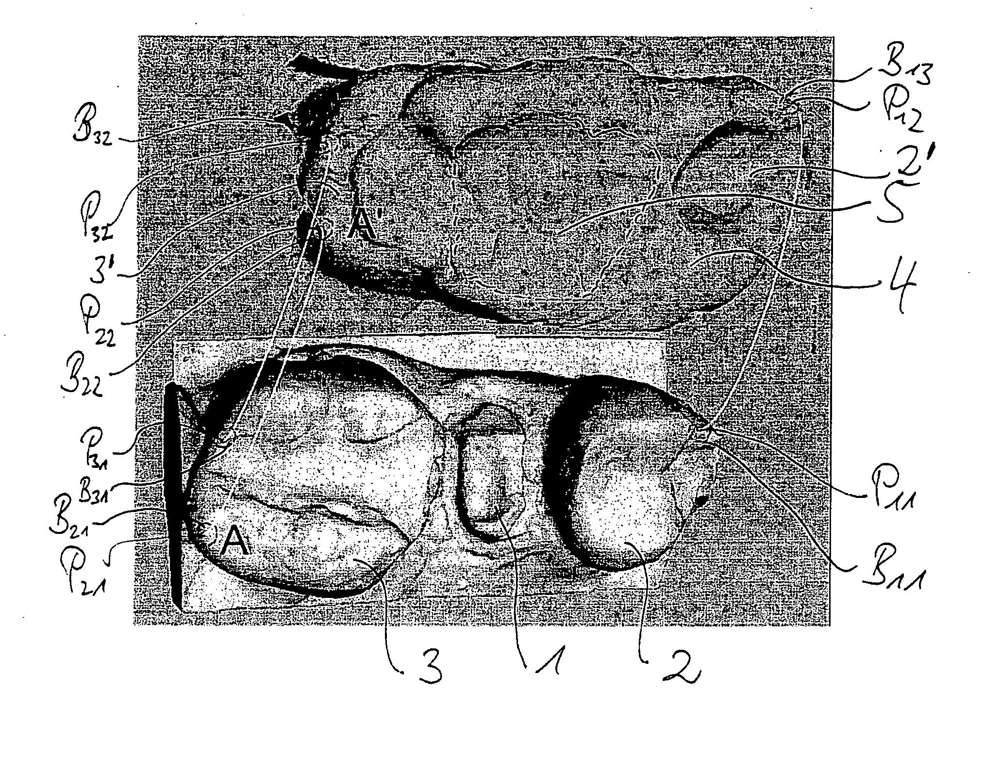
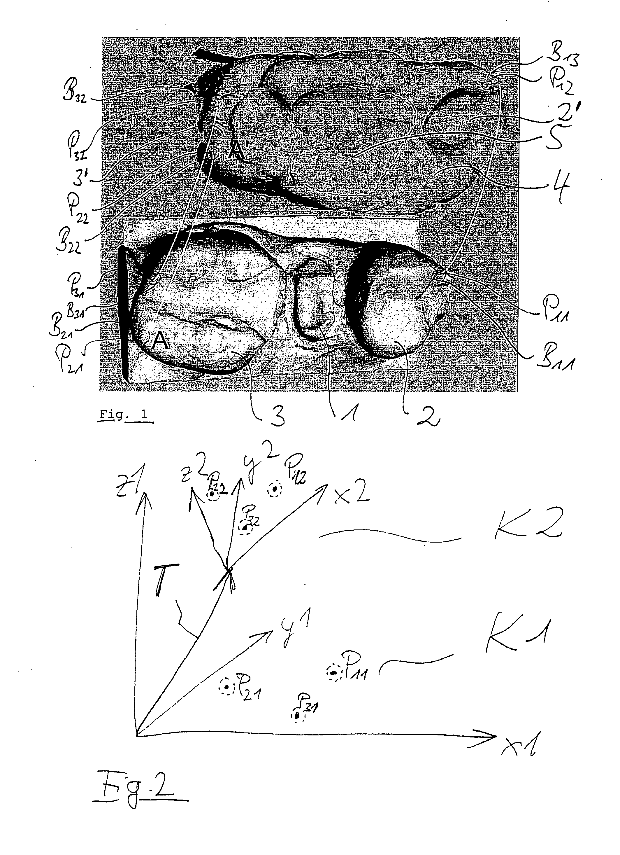
[0036] Two 3D models A and A′ are shown in FIG. 1. The 3D model A is a digital representation of a prepared tooth 1 with its adjacent teeth 2, 3. The 3D model A′ is a data representation in approximately the same preparation site, wherein, however, an impression 5 of the opposite jaw is contained in an impression compound 4 and wherein the adjacent teeth 2′, 3′ are predominately covered by the impression compound 4. Parts of the impression 5 should be taken into account when designing a dental prosthetic item, in this case the chewing surface in said impression 5. Up to this point, the two 3D models A, A′ do not yet have any spatial relationship to each other. By comparing distinctive surface points or regions, one can see with the naked eye that there are surface points or regions on the surface that correspond to each other in the two models. In particular, the surfaces are edges or crests.

[0037] Both of the 3D models A, A′ are represented at the same degree of magnification and ...


PUM


Abstract

Disclosed is a method for designing tooth surfaces of a digital dental prosthetic item existing as a 3D data set using a first 3D model of a preparation site and/or of a dental prosthetic item and a second 3D model, which second model comprises regions which match some regions on the first 3D model and regions which differ from other regions of the first 3D model, the non-matching regions containing some of the surface information required for the dental prosthetic item, wherein at least three pairs (P1, P2, P3) of points (P11, P12; P21, P22; P31, P32) corresponding to each other are selected on the matching region on the first 3D model (A) and the second 3D model (A′), that the positional correlation of the second 3D model with reference to the first 3D model is determined with reference to the at least three pairs (P1, P2, P3), and that portions of the non-matching regions of the first and second 3D models are implemented for designing the tooth surface of the dental prosthetic item taking into consideration the positional correlation of these models relative to each other.

Description

CROSS-REFERENCE TO RELATED APPLICATIONS [0001] This application claims the priority of German Application No. 10 2005 011 066.5, filed Mar. 8, 2005, and is related to U.S. Provisional Application No. 60 / 794,612, filed Dec. 13, 2005, the priority of which is hereby claimed.TECHNICAL FIELD [0002] This invention relates to part of a process for the manufacture of dental prosthetic items in a dental CAD system. [0003] In the dental CAD / CAM system “CEREC” (registered trademark of Sirona Dental Systems GmbH, Germany), the operator performs a 3D scan of a prepared tooth and its adjacent teeth, from which scan a data representation of the 3D model of the region scanned is produced in the memory unit of a computer and displayed. DESCRIPTION OF THE RELATED ART [0004] In order to copy, say, the chewing surface of a tooth prior to preparation, the tooth can be scanned prior to preparation, together with the adjacent teeth, and a corresponding 3D model can then be computed. [0005] Another varian...

Claims


Application Information

Patent Timeline
IPC IPC(8): G06K9/00G06T15/00A61C19/00
CPCA61C13/0004G06T19/20G16H20/40
Inventor ORTH, ULRICHWEDLER, VOLKER
Owner SIRONA DENTAL SYSTEMS
Why Eureka
Try Eureka