
Portable cervical traction device

a traction device and portable technology, applied in the field of portable traction devices, can solve the problems of inconvenient home use, high cost of equipment needed for traction, and the distraction or separation of vertebrae of spinal traction, and achieve the effect of sufficiently low cost portable traction devices for home us

Inactive Publication Date: 2006-09-14
ENCORE MEDICAL ASSET CORP
View PDF80 Cites 16 Cited by
  • Summary
  • Abstract
  • Description
  • Claims
  • Application Information

AI Technical Summary

Benefits of technology

Enables effective and prolonged spinal decompression therapy in a home setting by maintaining consistent traction force without the need for continuous air supply, addressing the limitations of previous devices in terms of cost, weight, and effectiveness.

Problems solved by technology

When correctly performed, spinal traction can cause distraction or separation of the vertebral bodies, a combination of distraction and gliding of the facet joints, tensing of the ligamentous structures of the spinal segment, widening of the intervertebral foramen, straightening of spinal curvature and stretching of the spinal musculature.
The equipment necessary for performing traction, however, has typically been expensive and thus only available to a patient in a therapist's office.
Attempts to create a sufficiently low cost portable traction device for home use have thus far produced unsatisfactory results.
Hydraulic cylinders have the disadvantage of the weight of the hydraulic fluid.
Pneumatic cylinders with low pressure inputs typically can not maintain an adequate traction force for a sufficient period of time to be effective in a traction device.
These pump and sensor configurations add cost, weight and complexity to the traction device.
Consequently, small input pressure devices require large diameter cylinders to generate the necessary output traction forces.
Larger diameter cylinders, when used with low pressure input devices, are more prone to leak, thereby further complicating the problem of maintaining a constant traction force for a prolonged period of time.

Method used


Image

  • Portable cervical traction device
  • Portable cervical traction device
  • Portable cervical traction device

Examples


first embodiment

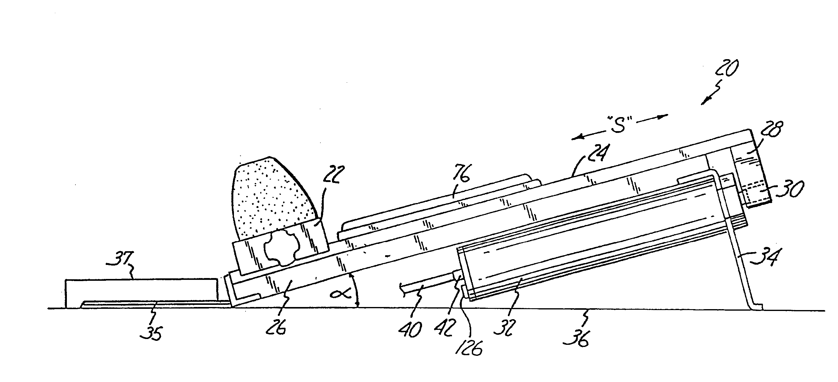
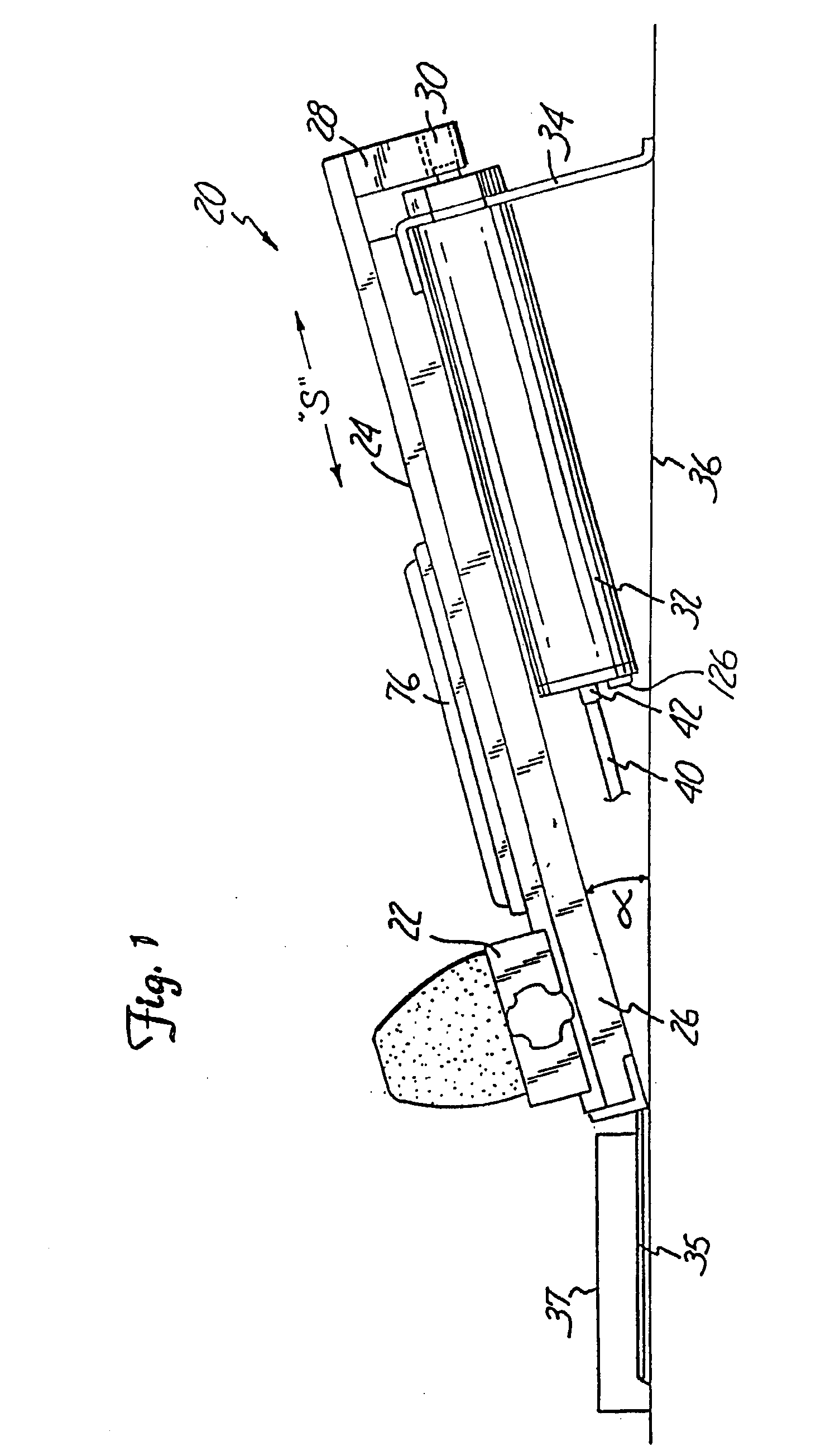
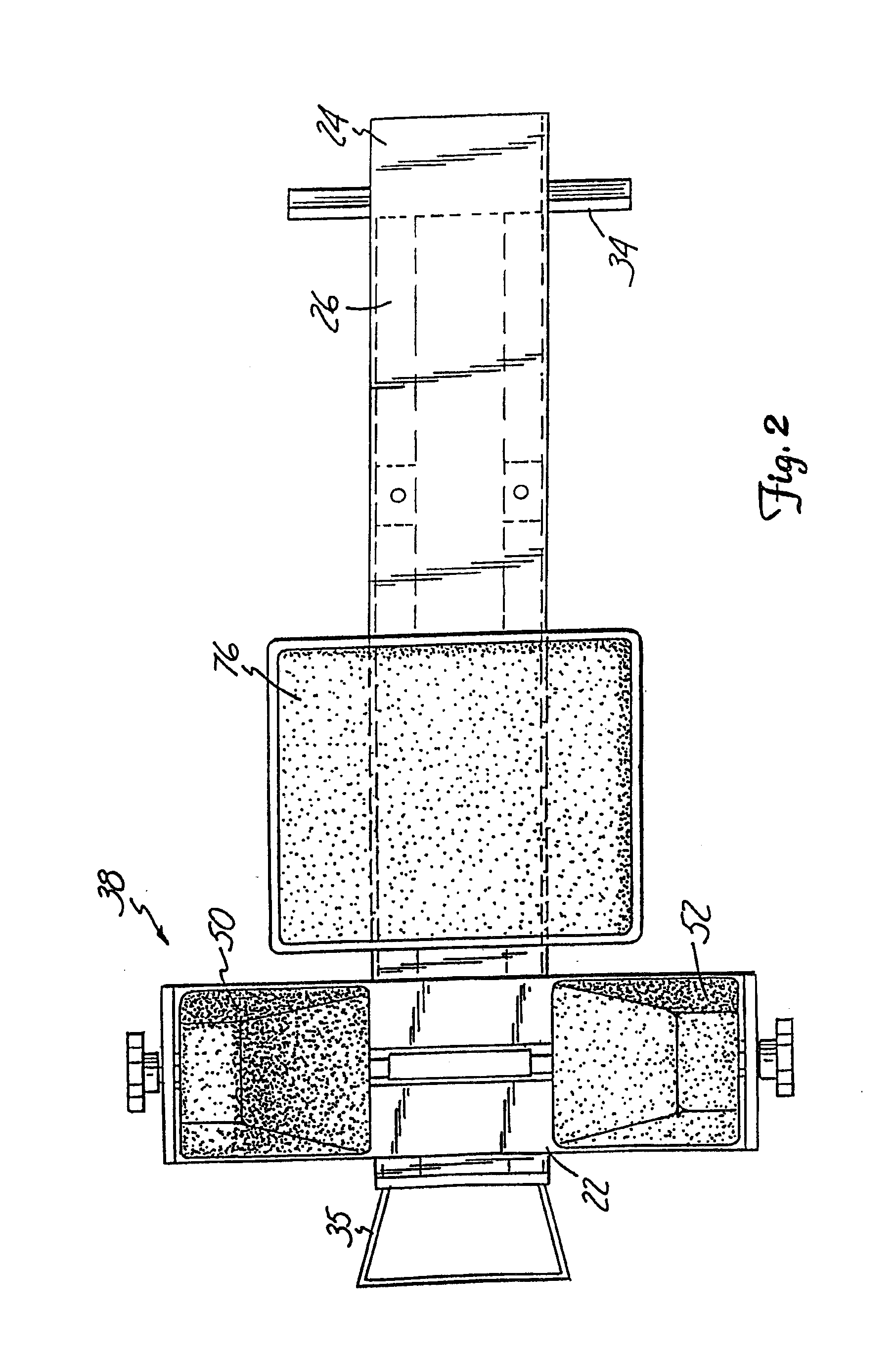
[0040]FIG. 8 illustrates a portable, lumbar traction device 140 in which the pneumatic cylinder 32 is attached to a portable traction device 140. The portable, lumbar traction device 140 includes a frame 150 retaining a support surface 152. In a first embodiment, a pelvic belt 142 retains the patient's pelvis to a sliding portion 154, which slides along track 156. The pneumatic cylinder 32 mounted to the frame 150 is coupled to the sliding portion 154 so that the sliding portion 154 moves along the track 156, creating a traction force “F” when the cylinder 32 is pressurized. A counter traction belt 148 provides a passive counter traction force on the patient's lower rib cage. The pneumatic cylinder 32 preferably maintains a static traction force of greater than 445 N (100 lbs.) for a period in excess of 10 minutes, and preferably, a static traction force of greater than 890 N (200 lbs.) for a period in excess of 20 minutes, without the need to supply additional pressurized air. It w...

second embodiment

[0041] In a second embodiment, pelvic belt 142 is engaged with the pneumatic cylinder 32 by a cable 144 and pulley 146 configuration mounted at the foot of the portable traction device 140. Counter-traction belt 148 provides a passive counter traction force on the patient's lower rib cage to restrain the patient in a fixed position relative to the portable traction device 140. When the patient activates the pneumatic cylinder 32 as discussed above, the cable 144 is retracted, creating a traction force “F” on the waist belt 142 and the patient's pelvic region. In either of the above embodiments, the counter traction belt 148 may also be coupled to the pneumatic cylinder 32 to provide an active counter traction force in a direction opposite to “F” on the patient.

[0042]FIGS. 9a-9c illustrate an alternate embodiment of a portable, lumbar traction device 200 positioned directly on the support surface 36. Upper body support platform 202 includes a frame 204 supporting a support surface 20...


PUM


Abstract

Low-cost, light weight portable cervical traction or spinal decompression devices for home use by a patient. A carriage is slidable along a portion of a support structure parallel to a longitudinal axis. The carriage includes a restraining mechanism adapted to releasably restrain a portion of a patient's body to the carriage. The pneumatic traction force generating apparatus is operatively coupled to move the carriage relative to the support structure when in a pressurized state. The pneumatic traction force generating apparatus is adapted to maintain a generally static traction force during a treatment period when in the pressurized state without additional pressurized air being supplied. A hand pump operated by the patient is fluidly connected to the pneumatic traction force generating apparatus to inject pressurized air. The hand pump is capable of injecting at least 138 kPa (20 psi) of pressure into the pneumatic traction force generating apparatus. A pressure relief mechanism operated by the patient is adapted to release pressure from the pneumatic traction force generating apparatus.

Description

RELATED APPLICATIONS [0001] The present application is a continuation of U.S. patent application Ser. No. 10 / 751,688 filed Jan. 5, 2004 (allowed); which is a continuation of U.S. patent application Ser. No. 10 / 320,589 filed Dec. 16, 2002 (U.S. Pat. No. 6,899,690), which is a continuation of U.S. patent application Ser. No. 08 / 817,444 (U.S. Pat. No. 6,506,174), which is a continuation of PCT / US95 / 14217 filed Oct. 31, 1995, which claims priority to and is a continuation-in-part of U.S. patent application Ser. No. 08 / 334,189 filed Nov. 3, 1994 (abandoned), all of which are hereby incorporated by reference.FIELD OF THE INVENTION [0002] The present invention is directed to a portable traction device powered by a pneumatic traction force generating apparatus. BACKGROUND OF THE INVENTION [0003] Traction, also referred to as spinal decompression, is widely used to relieve pressure on inflamed or enlarged nerves. While traction is applicable to any part of the body, cervical and lumbar or sp...

Claims


Application Information

Patent Timeline
Patent Type & Authority Applications(United States)
IPC IPC(8): A61F5/00A61F5/04
CPCA61F5/04A61H1/0222A61H1/0296A61H2201/0157A61H2201/0161A61H2201/0192A61H2201/1246A61H2201/1607A61H2201/1628A61H2201/1664A61H2201/5053A61H2203/0456
Inventor SAUNDERS, H. DUANESTULTZ, MARK R.
Owner ENCORE MEDICAL ASSET CORP
Learn More