Systems, methods, and computer-readable media for invoking an electronic ink or handwriting interface

a text input and computer-readable media technology, applied in the field of user interfaces, methods, systems, computer-readable media for activating and/or displaying text input systems, can solve problems such as error messages, inability of application programs to accept data in a format other than machine-generated text, and ignored inpu

Active Publication Date: 2006-09-21
MICROSOFT TECH LICENSING LLC
View PDF5 Cites 121 Cited by
  • Summary
  • Abstract
  • Description
  • Claims
  • Application Information

AI Technical Summary

Benefits of technology

[0011] Aspects of this invention relate to user interfaces, methods, systems, and computer-readable media for activating and / or displaying a text input system on a display device. Such user interfaces, systems, and methods may include: (a) displaying a text input system activation target at a first location on the display device, wherein the text input system activation target is displayed at a first size and / or with a first appearance characteristic at least when a user input device hovers proximate to the first location, wherein the first location is changeable in response to user input; (b) receiving a first user input directed to the text input system activation target (e.g., a pen tap, an extended hover action, etc.); and (c) activating a text input system in response to the first user input. Such user interfaces, methods, and systems further may include: (d) displaying a pre-interaction condition of the text input system activation target, wherein the pre-interaction condition includes at least one display condition selected from the group consisting of: a display condition in which no text input system activation target is visible, a display condition in which a text input system activation target of a second size is visible, and a display condition in which a text input system activation target having a second appearance characteristic is visible; (e) receiving a second user input directed to the text input system activation target in the pre-interaction condition; and (f) changing an appearance of the text input system activation target from the pre-interaction condition to the first size and / or the first appearance characteristic in response to the second user input. The second size of the activation target, in at least some manner or dimension, may be smaller than the corresponding dimension(s) of the activation target at the first size. The second appearance characteristic of the activation target, in at least some examples, may be a plain text, faded, lightened, or grayed out version of the activation target as compared with the activation target with the first appearance characteristic. The text input system activation target, in at least some examples of the invention, may be freely positionable by the user, e.g., at any location along the window or screen edges. After use of the text input system, it may be closed or “re-stowed” along the window or screen edge, at its location of last use, and in at least some examples of the invention, the text input system will re-deploy for its next use in the same form, format, and / or state in which it was last used. Still additional aspects of this invention relate to computer-readable media including computer-executable instructions stored thereon for providing various user interfaces for activating and / or displaying a text input system, performing various text input system activating and / or displaying methods, and / or operating various text input activation and / or displaying systems.

Problems solved by technology

Not all application programs, however, have been designed to accept and / or are capable of accepting user input in the form of electronic ink and / or via an electronic pen.
For example, many application programs are incapable of accepting data in a format other than machine-generated text (e.g., input via a conventional keyboard, downloaded, or input in some other manner).
When pen-based computing system users open and use such restricted input application programs, attempts to enter electronic ink input into areas or fields that are incapable of accepting such input will result in error messages, ignored input, erroneous input, lost input, and / or other input issues.
Such input entry difficulties constitute a source of frustration for users of pen-based computing systems.
If this tablet PC user has only the computing system's pen or stylus available as an input device, he / she will be incapable of inputting data into this electronic document and / or otherwise interacting with this application program.
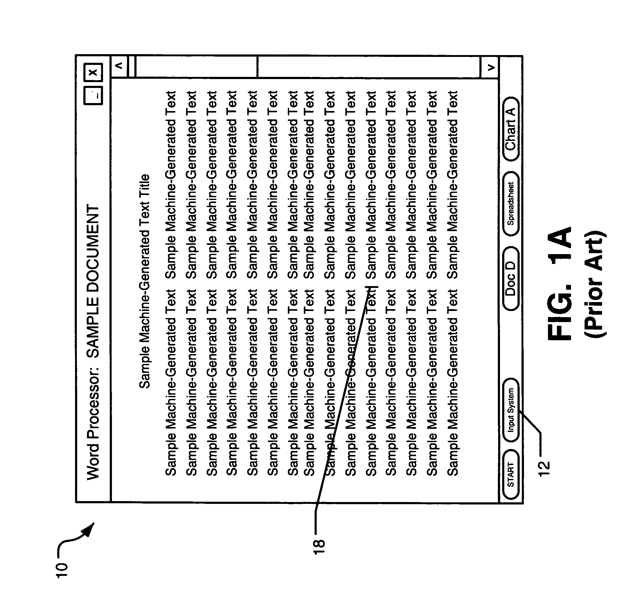
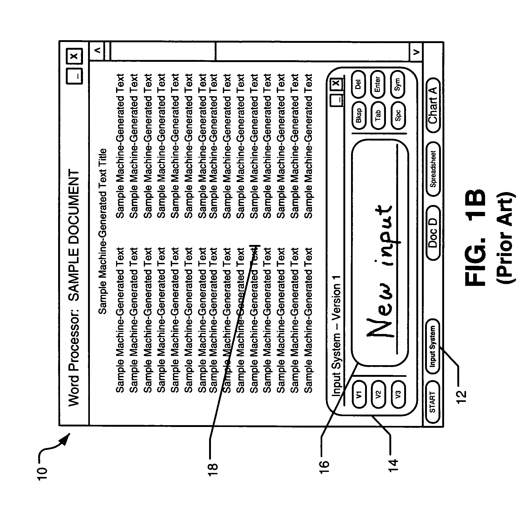
Many users find this location somewhat unnatural and / or inconvenient to use (e.g., because many users interact with and operate in the top half to two-thirds of the display screen 10 in a pen-based computing system, locating the text input system icon in the lowest 5% of the display screen 10 has not been found to be very natural or convenient).
Additionally, in many instances, users tended to forget the purpose of the icon 12 and / or would activate it only after searching for it (the appearance of the icon 12 in some conventional systems (e.g., as a tiny picture of a keyboard with no associated text) was not readily visible or identifiable by users, thereby failing to provide an immediate visual clue as to the purpose of icon 12).
These factors make use of input panel 14 seem a substantial and inconvenient interruption in the data entry process.
Additionally, in at least some circumstances (e.g., for application programs and / or users that prefer to hide this lowermost toolbar), location of the icon 12 and / or activation of the interface panel 14 can be difficult or even impossible.
The changes required to allow this type of resizing and position shifting can be somewhat disorienting and disruptive, and it can result in inaccurate data displays.

Method used


Image

  • Systems, methods, and computer-readable media for invoking an electronic ink or handwriting interface
  • Systems, methods, and computer-readable media for invoking an electronic ink or handwriting interface
  • Systems, methods, and computer-readable media for invoking an electronic ink or handwriting interface

Examples


Embodiment Construction

I. Terms

[0018] The following terms are used in this specification and, unless otherwise specified or clear from the context, the terms have the meanings provided below:

[0019]“Ink” (also called “digital ink” or “electronic ink”)—A sequence or set of handwritten strokes. A sequence of strokes may include strokes in an ordered form. The sequence may be ordered in any suitable manner, such as by the time the stroke was captured and / or by where the stroke appears on a page. Other orders are possible. Electronic ink information may be stored in any desired manner, such as in an “ink serialized format,” e.g., a format used for creating, storing, displaying, and manipulating electronic ink data in the Microsoft® Windows XP Tablet PC Edition Version 2002 operating system and / or the Microsoft® Windows Journal software application.

[0020]“Point”—Information defining a location in space. For example, a point may be defined relative to a capturing space (for example, points on a digitizer) and / ...


PUM


Abstract

User interfaces, methods, systems, and computer-readable media for activating and / or displaying text input systems on display devices may include: (a) displaying a text input system activation target at a user changeable location on a display device; (b) receiving user input directed to the activation target; and (c) activating a text input system in response to the user input. Such user interfaces, methods, and systems further may include (d) displaying a pre-interaction condition of the activation target; (e) receiving user input directed to the activation target in this pre-interaction condition; and (f) changing an appearance of the activation target from the pre-interaction condition to a larger size and / or a different visual appearance in response to this user input. Additional aspects of this invention relate to computer-readable media for providing user interfaces, systems, and methods as described above.

Description

FIELD OF THE INVENTION [0001] The present invention relates to user interfaces, methods, systems, and computer-readable media for activating and / or displaying a text input system on a computing system. In at least some examples of this invention, the computing system may constitute a pen-based computing system that is capable of receiving, processing, and / or displaying electronic ink data. BACKGROUND [0002] As the role of computers has expanded, various different techniques have been developed for entering data into computers. Recently, pen-based computing systems (such as tablet PCs, personal digital assistants, and the like) have gained popularity. One particularly useful technique for entering data in such pen-based computing systems is through the use of handwriting. By writing with a stylus, electronic pen, or other user input device on a digitizer, e.g., to produce “electronic ink,” a pen-based computer user can forego the bulk and / or inconvenience associated with use of a con...

Claims


Application Information

Patent Timeline
Patent Type & Authority Applications(United States)
IPC IPC(8): G09G5/00
CPCG06F3/03545G06F3/0481G06F3/0416G06F3/02G06F3/04886G06F3/04162F42B12/48F42B3/195
Inventor GARSIDE, ADRIAN J.JONES, F. DAVIDCLOW, JOSH A.TANDOG, JUDY C.KEELY, LEROY B.SCHULTZ, TRACY DIANNE
Owner MICROSOFT TECH LICENSING LLC
Why Eureka
Try Eureka