Reciprocating compressor

a compressor and reciprocating technology, applied in the direction of positive displacement liquid engines, pumps, machines/engines, etc., can solve the problems of deteriorating motor performance, and achieve the effect of reducing the width of the compressor

Inactive Publication Date: 2006-09-21
LG ELECTRONICS INC
View PDF5 Cites 57 Cited by
  • Summary
  • Abstract
  • Description
  • Claims
  • Application Information

AI Technical Summary

Benefits of technology

[0020] Therefore, it is an object of the present invention to provide a reciprocating compressor capable of moving a resonant spring horizontally and straight forwardly by reducing a torsion moment of the resonant spring, reducing a width of the compressor, and maintaining a concentricity of a driving unit and a compression unit.

Problems solved by technology

Because of this, it is difficult for the piston 124 to keep its linear movement, so performance of a motor is deteriorated.

Method used


Image

  • Reciprocating compressor
  • Reciprocating compressor
  • Reciprocating compressor

Examples


Embodiment Construction

[0035] A first embodiment of the present invention will now be described with reference to the accompanying drawings.

[0036] There can be a plurality of embodiments of the reciprocating compressor in accordance with the present invention, and a preferred embodiment will now be described.

[0037]FIG. 3 is a sectional view of a reciprocating compressor according to the present invention.

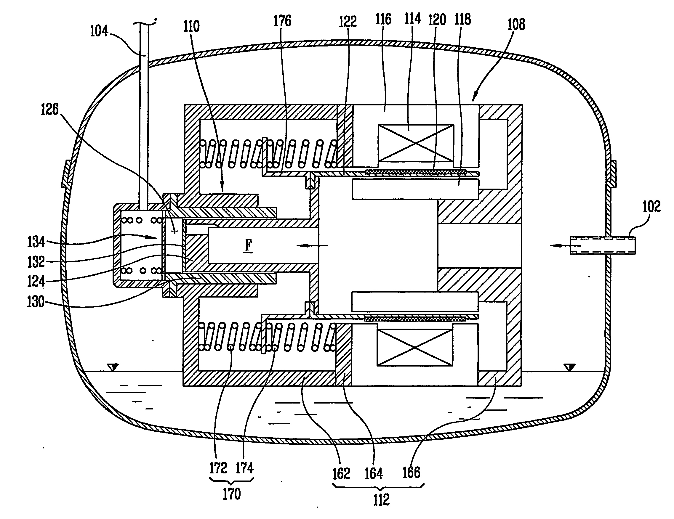
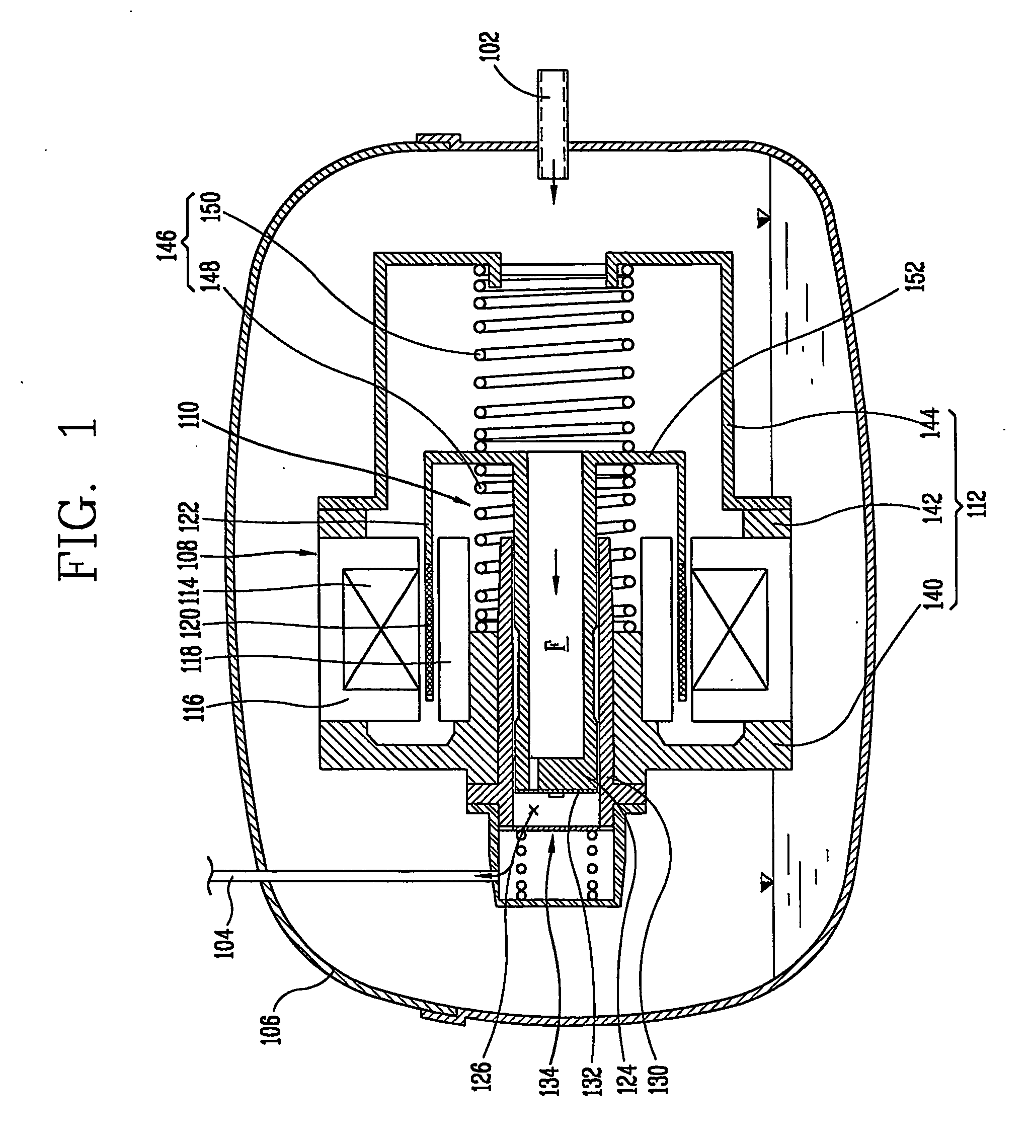
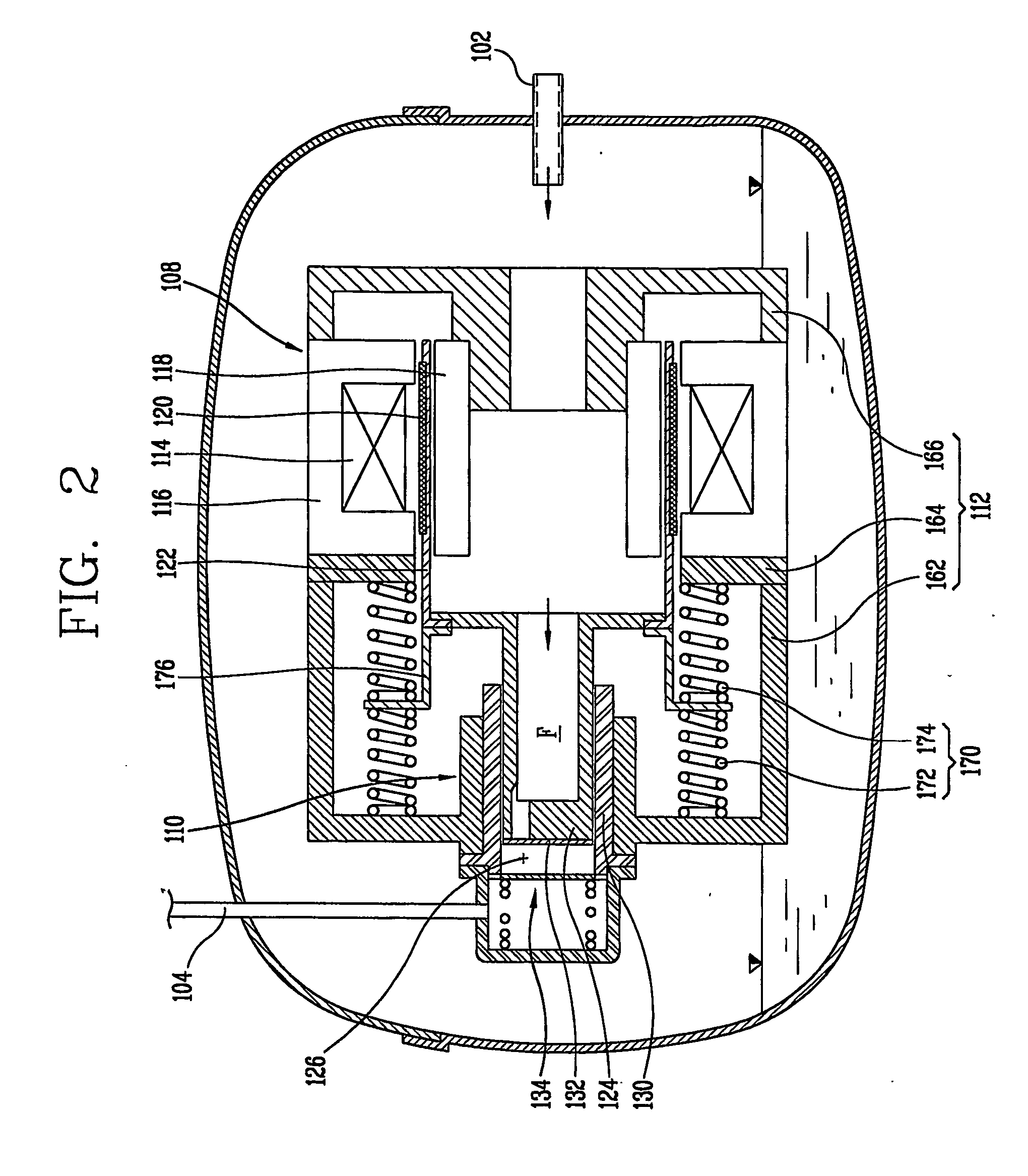
[0038] The reciprocating compressor of the present invention includes a casing 14 to which a suction pipe 10 and a discharge pipe 12 are connected respectively; a driving unit 16 disposed in the casing 14 and generating a reciprocal movement force; a compression unit 18 disposed in the driving unit 16 and compressing a fluid by being transmitted the reciprocal movement force of the driving unit 16; a support unit 20 supporting the driving unit 16 and the compression unit 18; a resonant spring assembly 24 installed at the support unit 20 and inducing a resonant movement of the piston 22 by providing an ...


PUM


Abstract

A reciprocating compressor includes a driving unit (16) having an outer stator (26) and an inner stator disposed at a predetermined air gap there between, and a moving member positioned between the outer stator (26) and the inner stator (28) and linearly and reciprocally moved; a compression unit (18) having a cylinder (38) fixed at an inner circumferential surface of the inner stator (28) and a piston (22) linearly moved in the cylinder (38) by being connected to the moving member, a support portion (20) supporting the compression unit (18) and the driving unit (16); and a resonant spring unit positioned (24) at a rear portion of the driving unit (16), disposed at the support portion (20), and inducing a resonant movement of the piston (22). Therefore, a resonant spring (62,64) of the compressor can be moved horizontally and straight forwardly by reducing a torsion moment of the resonant spring (62,64), a width of the compressor can be reduced, and a concentricity of a driving unit (16) and a compression unit can be maintained.

Description

TECHNICAL FIELD [0001] The present invention relates to a reciprocating compressor, and particularly to a reciprocating compressor that can be compact in size and having improved performance. BACKGROUND ART [0002]FIG. 1 is a sectional view showing a reciprocating compressor in accordance with one example of a conventional art. [0003] A conventional reciprocating compressor includes a close casing to which a suction pipe 102 and a discharge pipe 104 are connected respectively; a driving unit 108 disposed in the casing 106 and generating a reciprocal movement force; a compression unit 110 transmitted the reciprocal movement force generated at the driving unit 108 and compressing a fluid; a support portion 112 supporting the driving unit 108 and the compression unit 110. [0004] The driving unit 108 includes an outer stator 116 fixed at the support portion 112 and having a winding coil 114 to which power is applied; an inner stator 118 disposed at an inner circumferential surface of the...

Claims


Application Information

Patent Timeline
Patent Type & Authority Applications(United States)
IPC IPC(8): F04B17/04F04B35/04
CPCF04B35/045
Inventor HYEON, SEONG-YEOL
Owner LG ELECTRONICS INC
Why Eureka
Try Eureka