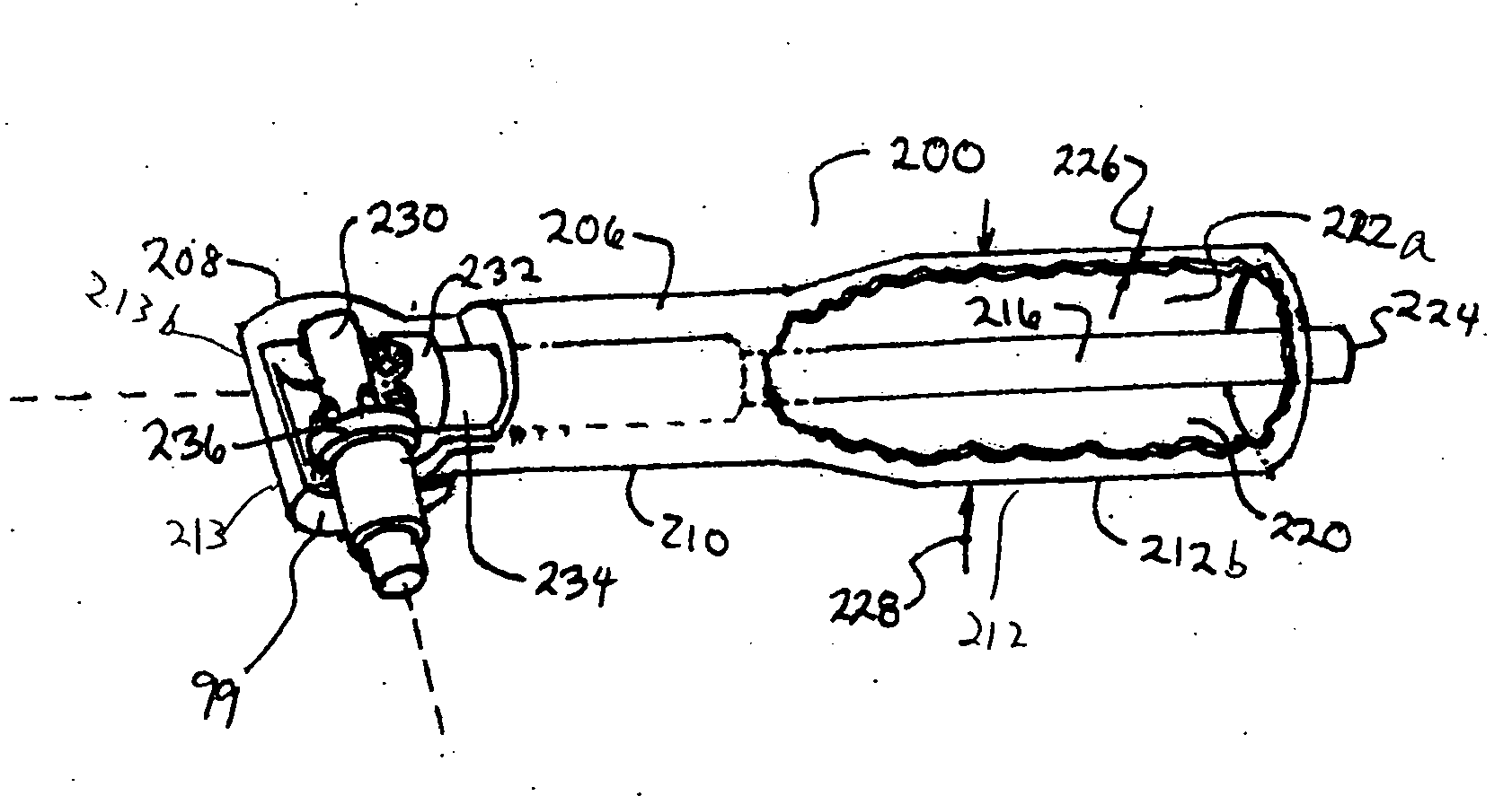
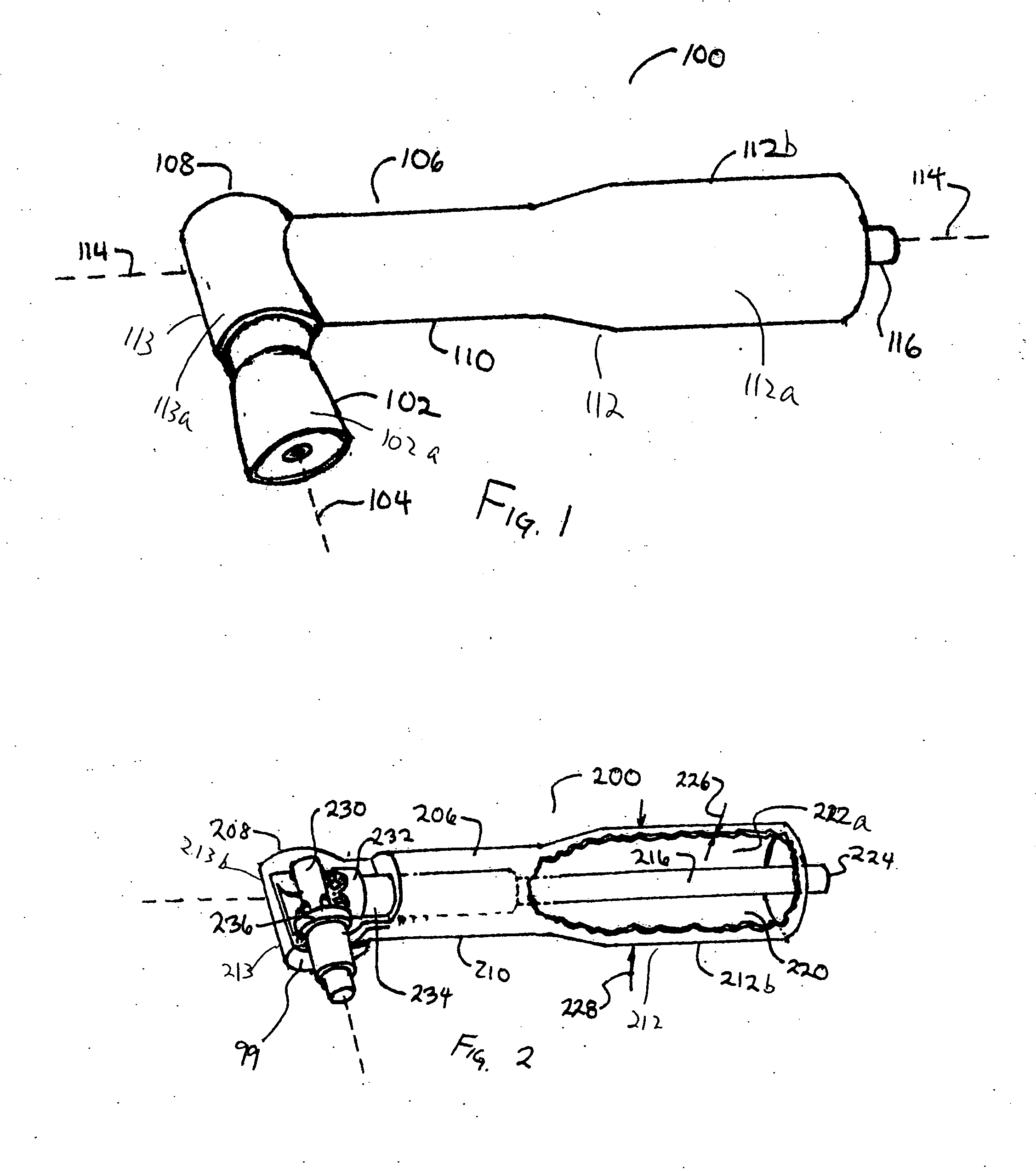
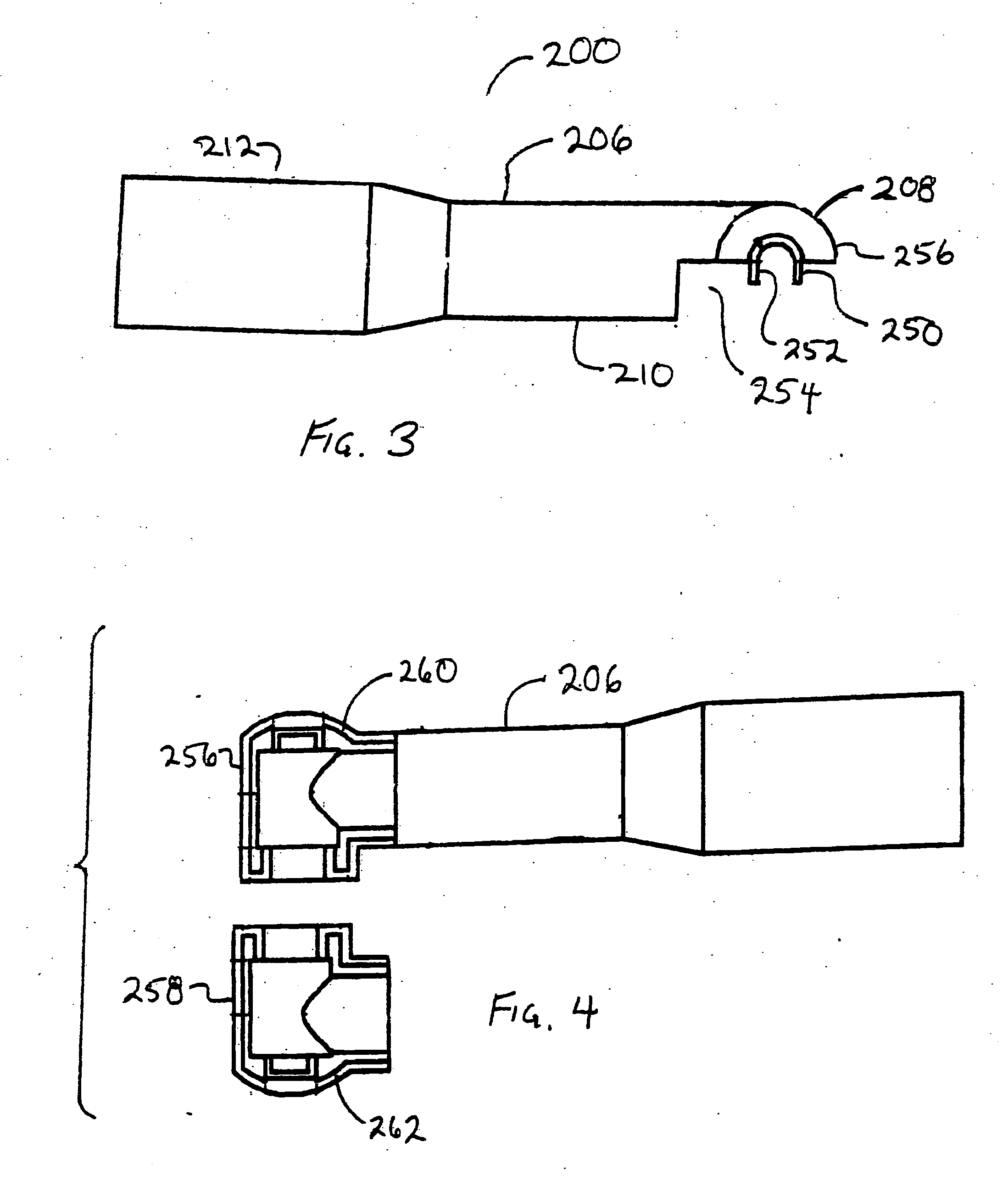
Prophylaxis angles and cups

a prophylaxis angle and cup technology, applied in the field of dental tools, can solve the problems of difficult retention of polishing paste within the cup, the tendency of some cups to become detached from the prophylaxis angle, etc., and achieve the effect of strengthening the attachment force and improving the attachment for

Inactive Publication Date: 2006-09-21
ZILA INC
View PDF30 Cites 25 Cited by
  • Summary
  • Abstract
  • Description
  • Claims
  • Application Information

AI Technical Summary

Benefits of technology

[0011] In one embodiment, the formation may be a horizontal through hole through the side of the shaft part. so that the material of the cup may seep through the hole and serves as an additional anchor to strengthen the attachment forces between the cup and the shaft part. In one aspect, the shaft part may also have a cap over its proximal end.
[0012] In another embodiment, the formation in the shaft part may be a vertical through hole extending for a length of the shaft part so that the material of the cup may fill the hole and serves as an additional anchor to strengthen the attachment forces between the cup and the shaft part.

Problems solved by technology

A common problem is the difficulty in retaining the polishing paste within the cup as the cup is rotated against the tooth.
Another common problem is the tendency of some cups to become detached from the prophy angle, either during rotation or during loading of polishing paste.

Method used


Image

  • Prophylaxis angles and cups
  • Prophylaxis angles and cups
  • Prophylaxis angles and cups

Examples


Embodiment Construction

[0058] The detailed description set forth below is intended as a description of the presently exemplified invention provided in accordance with aspects of the present invention and is not intended to represent the only forms in which the present invention may be prepared or utilized. The description sets forth the features and the components of the invention and related systems of the present invention and it is to be understood, however, that the same or equivalent functions and components included in the description may be accomplished by different embodiments that are also intended to be encompassed within the spirit and scope of the invention.

[0059] Unless defined otherwise, all technical and scientific terms used herein have the same meaning as commonly understood to one of ordinary skill in the art to which this invention belongs. Although any methods, devices and materials similar or equivalent to those described herein can be used in the practice or testing of the invention...


PUM


Abstract

A prophy angle includes a driven shaft and a driving shaft. The driving shaft as an integrally molded crown gear disposed coaxially thereon. The driven shaft as a carousel gear including a plurality of pins, each pin having a longitudinal axis parallel to a longitudinal axis of the driving shaft. Each pin is coupled to the driving shaft by a fillet. The prophy angle includes a housing that has a major part and a minor part. The driving shaft is inserted into the housing from an open distal end of the major part. The driven shaft is also inserted into the housing at the open distal end of the major part. Thereafter, the minor part of the housing is connected to the major part of the housing to close the open distal end of the major part of the housing.

Description

CROSS-REFERENCE TO RELATED APPLICATIONS [0001] This application claims the benefit of U.S. provisional patent application, “Prophylaxis Angles and Cups” filed Mar. 14, 2005, Ser. No. 60 / 662037, the contents of which is hereby incorporated by reference.FIELD OF THE INVENTION [0002] This invention relates to dental tools. Specifically, this invention relates to dental or prophylaxis angles and cups used in tooth polishing. BACKGROUND OF THE INVENTION [0003] As part of dental hygiene, a patient's tooth is polished by a dental professional during a cleaning visit. Cups are used by dental professionals to carry a polishing paste. The polishing is accomplished by applying a prophylactic polishing paste to the teeth using a small rubber cup, commonly called a prophy cup. The prophy cup is filled or loaded with a prophylactic polishing paste and the filled cup is held against the surface of a tooth while the cup is mechanically rotated. The force of rotation forces the polishing paste to tr...

Claims


Application Information

Patent Timeline
IPC IPC(8): A61C3/06A61C1/18
CPCA61C17/005A61C17/00A61C1/18A61C1/12
Inventor ROSE, ERIC P.ULRICH, ANDREW B.SOSTARECZ, ZOLTAN
Owner ZILA INC
Why Eureka
Try Eureka